background image

I0119 REV.0

GENIUS s.r.l.

Via Padre Elzi, 32

24050 - Grassobbio

BERGAMO-ITALY

tel. 0039.035.4242511

fax. 0039.035.4242600

[email protected]

www.geniusg.com

Timbro rivenditore: / Distributor’s stamp: / Timbre de l’agent: /

Sello del revendedor: / Fachhändlerstempel:

Le descrizioni e le illustrazioni del presente manuale non sono
impegnative. GENIUS si riserva il diritto, lasciando inalterate le
caratteristiche essenziali dell’apparecchiatura, di apportare in
qualunque momento e senza impegnarsi ad aggiornare la
presente pubblicazione, le modifiche che essa ritiene conve-
nienti per miglioramenti tecnici o per qualsiasi altra esigenza di
carattere costruttivo o commerciale.

The descriptions and illustrations contained in the present
manual are not binding. GENIUS reserves the right, whils leav-
ing the main features of the equipments unaltered, to under-
take any modifications to holds necessary for either technical
or commercial reasons, at any time and without revising the
present publication.

Les descriptions et les illustrations du présent manuel sont
fournies à titre indicatif. GENIUS se réserve le droit d’apporter à
tout moment les modifications qu’elle jugera utiles sur ce
produit tout en conservant les caractéristiques essentielles,
sans devoir pour autant mettre à jour cette publication .

Las descripciones y las ilustraciones de este manual no
comportan compromiso alguno. GENIUS se reserva el derecho,
dejando inmutadas las características esenciales de los
aparatos, de aportar, en cualquier momento y sin
comprometerse a poner al día la presente publicación, todas
las modificaciones que considere oportunas para el
perfeccionamiento técnico o para cualquier otro tipo de
exigencia de carácter constructivo o comercial.

Die Beschreibungen und Abbildungen in vorliegendem
Handbuch sind unverbindlich. GENIUS behält sich das Recht
vor, ohne die wesentlichen Eigenschaften dieses Gerätes zu
verändern und ohne Verbindlichkeiten in Bezung auf die
Neufassung der vorliegenden Anleitungen, technisch bzw,
konstruktiv / kommerziell bedingte Verbesserungen
vorzunehmen.

DICHIARAZIONE CE DI CONFORMITÁ

Fabbricante:

GENIUS s.r.l.

Indirizzo:

Via Padre Elzi, 32
24050 - Grassobbio
BERGAMO - ITALIA

Dichiara che:

L'apparecchiatura elettronica JA383

è conforme ai requisiti essenziali di sicurezza
delle seguenti direttive:

73/23 CEE e successiva modifica 93/68/CEE.
89/336 CEE e successiva modifica 92/31 CEE e
93/68/CEE

Grassobbio, 1 Marzo 2002

L’Amministratore Delegato

D. Gianantoni

EC COMPLIANCE DECLARATION

Manufacturer:

GENIUS s.r.l.

Address:

Via Padre Elzi, 32
24050 - Grassobbio
BERGAMO - ITALY

Declares that:

the JA383 electronic

complies with the essential safety requirements of
the following Directives:

73/23 EEC and subsequent amendment 93/68 EEC.
89/336 EEC and subsequent amendments 92/31 EEC
and 93/68 EEC.

Grassobbio, 1 March 2002

Managing Director

D. Gianantoni

DÉCLARATION CE DE CONFORMITÉ

Fabricant:

GENIUS s.r.l.

Adresse:

Via Padre Elzi, 32
24050 - Grassobbio
BERGAMO - ITALIE

Déclare que

:

L'appareillage électronique JA383

est conforme aux règles de sécurité visées par les
directives suivantes:

73/23 CEE, modifiée 93/68 CEE.
89/336 CEE, modifiée 92/31 CEE et 93/68 CEE.

Note supplémentaire:

ces produits ont été soumis à des essais dans une configuration

typique homogène (tous les produits sont fabriqués par GENIUS

s.r.l.)

.

Grassobbio, le 1 Mars 2002

L’Administrateur Délégué

D. Gianantoni

DECLARACIÓN CE DE CONFORMIDAD

Fabricante:

GENIUS s.r.l.

Dirección:

Via Padre Elzi, 32
24050 - Grassobbio
BERGAMO - ITALIA

Declara que:

El equipo electrónico JA383

Cumple los requisitos esenciales de seguridad
de las siguientes directivas:

73/23 CEE y sucesiva modificación 93/68 CEE,
89/336 CEE y sucesivas modificaciones 92/31 CEE y
93/68 CEE.

Nota:

los productos mencionados han sido sometidos a pruebas en

una configuración típica homogénea (todo productos

fabricado por GENIUS s.r.l.)

.

Grassobbio, 1º de Marzo de 2002.

Administrador Delegado

D. Gianantoni

EG-KONFORMITÄTSERKLÄRUNG

Hersteller:

GENIUS s.r.l.

Adresse:

Via Padre Elzi, 32
24050 - Grassobbio
BERGAMO - ITALIEN

erklärt:

das elektronisch Gerät JA383

entspricht den wesentlichen
Sicherheitsbestimmungen folgender Richtlinien:

73/23 EWG und nachträgliche Änderung 93/68 EWG
89/336 EWG und nachträgliche Änderung 92/31 EWG
sowie 93/68 EWG

Anmerkung:

die o.g. produkte sind in einer typischen und einheitlichen weise

getestet (alle von GENIUS s.r.l. gebaute produkte).

Grassobbio, 1 März 2002

Der Geschäftsführer

D. Gianantoni

Note aggiuntive:

questi prodotti sono stati sottoposti a test in una configurazio-

ne tipica omogenea (tutti i prodotti di costruzione GENIUS s.r.l.)

.

Notes:

these products have been subject to testing procedures carried

out under standardised conditions (all products manufactured

by GENIUS s.r.l.)

.

Содержание JA383

Страница 1: ...AILS COULISSANTS 115V EQUIPO ELECTRÓNICO PARA PORTONES CORREDIZOS 115V ELEKTRONISCHES GERÄT FÜR SCHIEBETORE 115V ISTRUZIONI PER L USO NORME DI INSTALLAZIONE USE AND INSTALLATION INSTRUCTIONS INSTRUCTIONS POUR L EMPLOI NORMES D INSTALLATION INSTRUCCIONES PARA EL USO NORMAS DE INSTALACIÓN BETRIEBSANLEITUNG INSTALLATIONSVORSCHRIFTEN ...

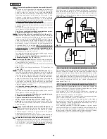
Страница 2: ...rfumesisaseriousdangertosafety 8 ThemechanicalpartsmustconformtotheprovisionsofStandardsEN12604 andEN12605 For non EU countries to obtain an adequate level of safety the Standards mentionedabovemustbeobserved inadditiontonationallegalregulations 9 GENIUS is not responsible for failure to observe Good Technique in the constructionoftheclosingelementstobemotorised orforanydeformation thatmayoccurdur...

Страница 3: ...da 0 a 4 min Forza di spinta Regolabile su 50 livelli Ingressi in morsettiera Open Open parziale Sicurezze in ap Sicurezze in ch Stop Costa Alimentazione Terra Ingressi in connettore Finecorsa apertura e chiusura Encoder Uscite in morsettiera Lampeggiatore Motore Aliment accessori 24 Vdc Lampada spia 24 Vdc Uscita temporizzata Failsafe Connettore rapido Innesto schede a 5 pin Minidec Decoder o ric...

Страница 4: ...ra e di chiusura dal rischio di impatto schiacciamento cesoiamento e convogliamento N B Se due o più dispositivi di sicurezza hanno la stessa funzione apertura chiusura apertura e chiusura costa i contatti vanno collegati in serie tra di loro fig 4 Devono essere utilizzati contatti N C Di seguito sono riportati i più comuni schemi di collegamento di fotocellule e dispositivi di sicurezza da fig 6 ...

Страница 5: ... obbligatorio il collegamento della scheda al conduttore di terra presente nell impianto Prevedere a monte del sistema un adeguato interruttore magnetotermico differenziale 4 3 Morsettiera J6 Motori e lampeggiatore fig 2 MOTORE morsetti 13 14 15 Collegamento Motore Nei motoriduttori dove è prevista la centrale incorporata questo collegamento è già precablato di serie Per la direzio ne di apertura ...

Страница 6: ...egare i contat ti N C in serie fig 4 Nota bene Se non vengono collegati dispositivi di sicurez za costa ponticellare gli ingressi EDGE e fig 5 Negativo alimentazione accessori morsetti 7 e 8 24 Vdc Positivo alimentazione accessori morsetti 9 e 10 Attenzione Il carico max degli accessori è di 500 mA Per calcolare gli assorbimenti fare riferimento alle istruzioni dei singoli accessori TX FSW Negativ...

Страница 7: ... igno rando la regolazione di coppia nell istan te iniziale del movimento Utile per ante pesanti Attiva Esclusa FRENATA FINALE Quando il cancello impegna il finecorsa di apertura o chiusura è possibile seleziona re un colpo di frenata per garantire l arre sto immediato dell anta Nel caso siano selezionati dei rallentamenti la frenata ini zierà alla fine dei medesimi Con valore la frenata è disabil...

Страница 8: ...na con il susse guirsi dei cicli La funzione può essere utilizzata per verifi care l uso della scheda o per usufruire della Richiesta assistenza Display Funzione Default STATO CANCELLO Uscitadallaprogrammazioneeritornoalla visualizzazione dello stato cancello vedi Cap 5 1 TEMPOLAVORO E opportuno impostare un valore di 5 10 secondi superiore al tempo necessario al cancello per andare dal finecorsa ...

Страница 9: ...to OPEN inibito Inverte in apertura per 2 2 Inverte in chiusura per 2 2 Tab 3 b LOGICA AP IMPULSI STATO CANCELLO OPEN A SICUREZZA AP CH SICUREZZE CHIUSURA SICUREZZE APERTURA STOP SICUREZZA COSTA Apre l anta e richiude dopo il tempo di pausa 1 Apre l anta per il tempo di apertura parziale e richiude dopo il tempo di pausa 1 APERTO in PAUSA OPEN B Nessun effetto Ricarica il tempo pausa 1 OPEN inibit...

Страница 10: ...A inibito Nessun effetto OPEN B inibito Chi u de l a nta Bl o cca i l funzi o namento Bl o cca i l funzi o namento Nessun effetto OPEN A inibito Nessun effetto COMANDI SEMPRE PREMUTI Nessun effetto OPEN B inibito Nessun effetto OPEN B inibito Nessun effetto OPEN A inibito Nessun effetto OPEN A inibito Nessun effetto OPEN A inibito Nessun effetto OPEN B inibito Bl o cca i l funzi o namento OPEN A B...

Страница 11: ...o 4 min Pause time Programmable from 0 to 4 min Thrust force Adjustable over 50 levels Terminal board inputs Open Partial opening Safety devices at opng Safety devices at clsng Stop Edge Power supply Earth On connector inputs Opening and closing limit switches Encoder Terminal board outputs Flashing lamp Motor 24 Vdc accessories power supply 24 Vdc indicator light Timed output Fail safe Rapid conn...

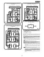
Страница 12: ...therefore it is suitable for protecting the opening and closing area against the risk of impact crushing shearing and dragging N B If two or more safety devices have the same function opening closing opening and closing edge the contacts must be connected to each other in series fig 4 N C contacts must be used The most common photocell and safety device lay outs are shown below from fig 6 to fig 1...

Страница 13: ... Neutral L 115 V power supply Line NB For correct operation the board must be connected to the earth conductor in the system Install an adequate differential thermal breaker upstream of the system 4 3 J6 Terminal board Motors and flashing lamp fig 2 MOTOR terminals 13 14 15 Motor connection In gearmotors with a built in control unit this connection is pre wired standard For leaf opening direction ...

Страница 14: ...devices are not connected jumper connect the EDGE and inputs fig 5 Negative for power supply to accessories terminals 7 and 8 24 Vdc Positive for power supply to accessories terminals 9 and 10 Important Accessories max load is 500 mA To calculate absorption values refer to the instructions for individual accessories TX FSW Negative for power supply to photocell transmitters terminal 11 If you use ...

Страница 15: ...he opening or closing limit switch a braking stroke can be selected to ensure the leaf is stopped immediately If decelerations are selected braking starts when they finish At value braking is disabled Time can be adjusted from to sec in 0 1 second steps E g if the display indicates braking time is 1 second Braking disabled from to Timed braking FAIL SAFE If this function is activated it enables a ...

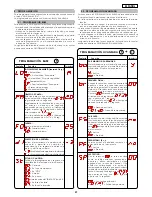
Страница 16: ...les proceed This function can be used to check use of the board or to exploit the Assistance request Display Function Default GATE STATUS Exitfromprogrammingandreturntogate status viewing see Chpt 5 1 WORK TIME We advise you to set a value of 5 to 10 seconds over the time taken by the gate to travel from the closing limit switch to the opening limit switch and vice versa This will protect the moto...

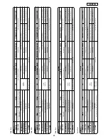
Страница 17: ... SAFETY DEVICE No effect OPEN disabled Reverses on opening for 2 2 Reverses on closing for 2 2 Table 3 b LOGIC AP PULSES GATE STATUS OPEN A OP CLOS SAFETY DEVICE CLOSING SAFETY DEVICES OPENING SAFETY DEVICES STOP EDGE SAFETY DEVICE Opens the leaf and closes it after pause time 1 Opens leaf for the partial opening time and closes after pause time 1 OPEN on PAUSE OPEN B No effect Reloads pause time ...

Страница 18: ...tops operati o n OPEN A disabled No effect OPEN B disabled Cl o ses the l e af Stops operati o n Stops operation No effect OPEN A disabled No effect CONTROLS ALWAYS HELD DOWN No effect OPEN B disabled No effect OPEN B disabled No effect OPEN A disabled No effect OPEN A disabled No effect OPEN A disabled No effect OPEN B disabled Stops operati o n OPEN A B di s abl e d Stops operati o n OPEN B disa...

Страница 19: ...rce de poussée Réglable sur 50 niveaux Entrées bornier Open Open partiel Sécurités en ouv Sécurités en ferm Stop Bord Alimentation Terre Entrées connecteur Fin de course ouverture et fermeture Encodeur Sorties bornier Feu clignotant Moteur Aliment accessoires 24 Vcc Lampe témoin 24 Vcc Sortie temporisée Failsafe Connecteur rapide Embrochage platine à 5 broches Minidec Decoder ou récepteurs RP Prog...

Страница 20: ... portail il est donc indiqué pour protéger la zone d ouverture et de fermeture contre le risque d impact d écrasement de cisaillement et d acheminement N B Si deux ou plusieurs dispositifs de sécurité ont la même fonction ouverture fermeture ouverture et fermeture bord il faut connecter les contacts en série entre eux fig 4 Il faut utiliser les contacts N F On reporte ci après les schémas les plus...

Страница 21: ...rect il est obligatoire de connecterlaplatineauconducteurdeterreprésentdansl installation Prévoir en amont du système un disjoncteur magnétothermique différentiel adéquat 4 3 Bornier J6 Moteurs et feu clignotant fig 2 MOTEUR bornes 13 14 15 Connexion Moteur Sur les motoréducteurs où on a prévu la centrale incorporée cette connexion est déjà pré câblée en série Pour la direction d ouverture du vant...

Страница 22: ...e sécurité connecter les contacts N F en série fig 4 Notabene Silesdispositifsdesécuritébordnesontpasconnectés ponter les entrées EDGE et fig 5 Négatif alimentation accessoires bornes 7 et 8 24 Vcc Positif alimentation accessoires bornes 9 et 10 Attention La charge maxi des accessoires est de 500 mA Pour calculer les absorptions se reporter aux instructions de chaque accessoire TX FSW Négatif alim...

Страница 23: ...note notes note notas anmerkung ...

Страница 24: ...note notes note notas anmerkung ...

Страница 25: ...note notes note notas anmerkung ...

Страница 26: ...note notes note notas anmerkung ...

Страница 27: ...e ou de fermeture on peut sélectionner un coup de frein pour garantir l arrêt immédiat du vantail Si on sélectionne des ralentissements le freinage commence à la fin de ces derniers Avec une valeur le freinage est invalidé Le temps est réglable de à s en pas de 0 1 seconde EX si l afficheur indique le temps de freinage correspond à 1 seconde Freinage exclu de à Freinage temporisé FAIL SAFE L activ...

Страница 28: ...cles La valeur affichée se met à jour avec la succession des cycles La fonction peut être utilisée pour vérifier l usage de la platine ou pour se servir de la Demande d assistance Afficheur Fonction Par défaut ÉTAT DU PORTAIL Sortie de la programmation et retour à l affichage de l état portail voir Chap 5 1 TEMPS DE FONCTIONNEMENT Il est opportun de sélectionner une valeur de 5 10secondessupérieur...

Страница 29: ...OPEN inhibé Invertit en ouverture pendant 2 2 Invertit en fermeture pendant 2 2 Tableau 3 b LOGIQUE AP IMPULSIONS ÉTAT PORTAIL OPEN A SÉCURITÉ OUV FERM SÉCURITÉS FERMETURE SÉCURITÉS OUVERTURE STOP SÉCURITÉ BORD Ouvre le vantail et referme au bout du temps de pause 1 Ouvre le vantail pendant le temps d ouverture partielle et referme après le temps de pause 1 OUVERT en PAUSE OPEN B Aucun effet Recha...

Страница 30: ...ue l e foncti o nnement Aucun effet Bl o que l e foncti o nnement OPEN A inhibé Aucun effet OPEN B inhibé Ferme l e vantai l Bl o que l e foncti o nnement Bl o que l e foncti o nnement Aucun effet OPEN A inhibé Aucun effet COMMANDES TOUJOURS ENFONCEES Aucun effet OPEN B inhibé Aucun effet OPEN B inhibé Aucun effet OPEN A inhibé Aucun effet OPEN A inhibé Aucun effet OPEN A inhibé Aucun effet OPEN B...

Страница 31: ...je Regulable en 50 niveles Entradas en regleta de bornes Open Open parcial Disp de seguridad enap Disp deseguridadencierre Stop Borde Alimentación Tierra Entradas en conector Fin de carrera apertura y cierre Encoder Salidas en regleta de bornes Destellador Motor Aliment accesorios 24 Vdc Luz testigo 24 Vdc Salida temporizada Fail safe Conector rápido Acoplamientotarjetasde5pinMinidec Decoderorecep...

Страница 32: ...os de apertura y cierre de la cancela por lo tanto es adecuado para proteger la zona de apertura y cierre contra el riesgo de impacto aplastamiento amputación y arrastre NOTA Si dos o más dispositivos de seguridad tienen la misma función apertura cierre apertura y cierre borde de seguridad los contactos deben conectarse en serie entre sí fig 4 Deben utilizarse contactos N C Seguidamente se incluye...

Страница 33: ... conexión de la tarjeta al conductor de tierra presente en la instalación Coloquen línea arriba del sistema un adecuado interruptor magnetotérmico diferencial 4 3 Regleta de bornes J6 Motores y destellador fig 2 MOTOR bornes 13 14 15 Conexión Motor En los motorreductores donde está prevista la central incorporada esta conexión ya esta precableada en serie Para la dirección de apertura de la hoja v...

Страница 34: ...ovimiento de las hojas Para instalar varios dispositivos de seguridad hay que conectar los contactos N C en serie fig 4 Nota Si no se conectan dispositivos de seguridad borde puenteen las entradas EDGE e fig 5 Negativo alimentación accesorios bornes 7 y 8 24 Vdc Positivo alimentación accesorios bornes 9 y 10 Atención La carga máxima de los accesorios es de 500 mA Para calcular las absorciones remí...

Страница 35: ...ierre se puede seleccionar un golpe para garantizar la parada inmediata de la hoja Si se seleccionan deceleraciones el frenado iniciará al final de las mismas Convalor elfrenadoestádeshabilitado El tiempo puede regularse de a seg a pasos de 0 1 segundos EJ si la pantalla indica el tiempo de frenado corresponde a 1 segundo Frenado excluido de a Frenado temporizado FAIL SAFE La activación de la func...

Страница 36: ...ilizarse para comprobar el uso de la tarjeta o para usar la Solicitud de asistencia Pantalla Función Por defecto ESTADO CANCELA Salida de la programación y regreso a la visualización del estado de la cancela véase Cap 5 1 TIEMPO DE TRABAJO Es conveniente programar un valor de 5 10 segundos superior al tiempo necesario para que la cancela vaya del fin de carrera de cierre al fin de carrera de apert...

Страница 37: ...to OPEN inhibido Invierte en apertura durante 2 2 Invierte en cierre durante 2 2 Tab 3 b LÓGICA AP IMPULSOS ESTADO CANCELA OPEN A DISP SEGURIDAD AP CI DIS SEGURIDAD CIERRE DIS SEGURIDAD APERTURA STOP SEGURIDAD BORDE Abre la hoja y cierra después del tiempo de pausa 1 Abre la hoja durante el tiempo de apertura parcial y cierra transcurrido el tiempo de pausa 1 ABIERTA en PAUSA OPEN B Ni n gún efect...

Страница 38: ... inhibido Ni n gún efecto OPEN B inhibido Cierra la hoja Bl o quea el funci o nami e nto Bloquea el funci o nami e nto Ni n gún efecto OPEN A inhibido Ni n gún efecto MANDOS SIEMPRE PRESIONADOS Ni n gún efecto OPEN B inhibido Ni n gún efecto OPEN B inhibido Ni n gún efecto OPEN A inhibido Ni n gún efecto OPEN A inhibido Ni n gún efecto OPEN A inhibido Ni n gún efecto OPEN B inhibido Bl o quea el f...

Страница 39: ...teilweise SicherheitsvorrichtungenbeimÖffn SicherheitsvorrichtungenbeimSchl Stop Leiste Versorgung Erdung EingängeinStecker EndschalterÖffnungsvorgangundSchließvorgang Encoder AusgängeaufKlemmenbrett Blinkleuchte Motor VersorgungZubehör24 Vdc Kontrollampe24Vdc getakteterAusgang Failsafe Schnellstecker SteckungKartenmit5StiftenMinidec DecoderoderEmpfangskartenRP Programmierung Nr 3Tasten F undDispl...

Страница 40: ...den Schutz des Öffnungs und des Schließbereiches vor Zusammenstößen und Quetschungen SchnittschädenundMitnahme Anmerkung habenzweiodermehrereSicherheitsvorrichtungendiegleiche Funktion Öffnungsvorgang Schließvorgang Öffnungsvorgang und Schließvorgang Leiste so werden die Kontakte in Reihenschaltung untereinander angeschlossen Abb 4 Hierbei sollten Arbeitskontakte verwendet werden Nachfolgendwerden...

Страница 41: ...er Anlage vorhandenen Erdungsleiter angeschlossen werden VordemSystemisteingeeigneterDifferential Wärmeschutzschalter zwischenzuschalten 4 3 Klemmenbrett J6 Motoren und Blinkleuchte Abb 2 MOTOR Klemmen 13 14 15 Anschluß Motor Bei den Getriebemotoren bei denen eine eingebaute Steuerzentrale vorgesehen ist ist dieser Anschluß bereits serienmäßig verkabelt Für die RichtungderÖffnungsbewegungdesFlügel...

Страница 42: ... dieBewegungderFlügel Um mehrere Sicherheitsvorrichtungen zu installieren werden die ArbeitskontakteinReihenschaltungangeschlossen Abb 4 Anmerkung werden keine Sicherheitsvorrichtungen Leiste angeschlossen so sind die Eingänge EDGE und zu überbrücken Abb 5 Negativ Versorgung Zubehörgeräte Klemmen 7 und 8 24 Vdc Positiv Versorgung Zubehörgeräte Klemmen 9 und 10 Achtung die maximale Last des Zubehör...

Страница 43: ...kann eine Bremsung angewähltwerden umdenunverzüglichenStopp des Flügels zu gewährleisten Sollten die Abbremsungenangewähltwordensein sobeginnt dieBremsungnachdiesen BeimWert istdieBremsungausgeschaltet DieZeitistzwischen und Sek einstellbar dieSchritteliegenbeijeweils0 1Sekunden Bsp zeigt das Display an so entspricht die Bremszeit1Sekunde Bremsung aus zwischen und getakteteBremsung FAILSAFE FUNKTI...

Страница 44: ...twirdbeiderAufeinanderfolge der Zyklen jeweils aktualisiert DieFunktionkannfürdieÜberprüfungdesEinsatzes der Karte oder für die Nutzung der Funktion Serviceaufforderung dienen Display Funktion Default STATUS TOR Verlassen der Programmierung und Rückkehr zur Anzeige des Status des Tors siehe Kap 5 1 ARBEITSZEIT Dieser Parameter sollte auf einen Wert eingestellt werden der um 5 10 Sekunden über der ...

Страница 45: ...rt um in Öffnungsvorgang für 2 2 Kehrt um in Schließvorgang für 2 2 Tab 3 b LOGIK AP IMPULSE STATUS TOR OPEN A SICHERHEIT ÖFF SCHL SICHERHEITEN SCHLIESSUNG SICHERHEITEN ÖFFNUNG STOP SICHERHEIT LEISTE Öffnet den Flügel und schließt nach Ablauf der Pausenzeit 1 Öffnet den Flügel für die Zeit der Teilöffnung und schließt erneut nach Ablauf der Pausenzeit 1 GEÖFFNET IN PAUSE OPEN B Keine Auswirkung Er...

Страница 46: ...rückt Keine Auswirkung OPEN B unterdrückt Schl i e ßt den Fl ü gel Blockiertden Betrieb Bl o cki e rt den Betrieb Keine Auswirkung OPEN A unterdrückt Keine Auswirkung STEUERUNGEN STETS GEDRÜCKT Keine Auswirkung OPEN B unterdrückt Keine Auswirkung OPEN B unterdrückt Keine Auswirkung OPEN A unterdrückt Keine Auswirkung OPEN A unterdrückt Keine Auswirkung OPEN A unterdrückt Keine Auswirkung OPEN B un...

Страница 47: ...or de impulso para evitar que la automación pueda ser accionada involuntariamente HINWEISE FÜR DEN INSTALLATIONSTECHNIKER ALLGEMEINE SICHERHEITSVORSCHRIFTEN 1 ACHTUNG Um die Sicherheit von Personen zu gewährleisten sollte die Anleitung aufmerksam befolgt werden Eine falsche Installation oder ein fehlerhafter Betrieb des Produktes können zu schwerwiegenden Personenschäden führen 2 BevormitderInstal...

Страница 48: ...nziali di sicurezza delle seguenti direttive 73 23 CEE e successiva modifica 93 68 CEE 89 336 CEE e successiva modifica 92 31 CEE e 93 68 CEE Grassobbio 1Marzo2002 L Amministratore Delegato D Gianantoni EC COMPLIANCE DECLARATION Manufacturer GENIUS s r l Address Via Padre Elzi 32 24050 Grassobbio BERGAMO ITALY Declares that the JA383 electronic complies with the essential safety requirements of th...

Отзывы: