Genie AWP-15S Скачать руководство пользователя страница 21

Part No. 37168

Genie AWP Super Series

19

Operator’s Manual

First Edition • Ninth Printing

Do Not Operate Unless:

You learn and practice the principles of safe

machine operation contained in this operator’s
manual.

1 Avoid hazardous situations.

2 Always perform a pre-operation

inspection.

3 Always perform function tests prior to use.

4 Inspect the workplace.

5 Only use the machine as it was intended.

Fundamentals

Using the machine for anything other than lifting
personnel and tools to an aerial work site is unsafe.

If more than one operator is expected to use a
machine at different times in the same work shift,
each operator is expected to follow all safety rules
and instructions in the operator’s manual. That
means every new operator should perform a pre-
operation inspection, function tests and a work
place inspection before using the machine.

Setup

1 Position the machine directly below the desired

work area.

2 Connect to the appropriate power source:

DC models: Connect battery pack.
AC models: Connect to a grounded 15A AC
power supply. Use a 12 gauge / 3.3mm

2

 3-wire

grounded extension cord no longer than
50 feet / 13 m.
Air models: Connect the airline.

3 Insert the key and turn to the 

ON

 position OR

turn to platform control.

4 Pull out the red Emergency Stop button at the

ground controls and twist to release the red
Emergency Stop at the platform controls. Be
sure the power light is on or the air pressure
gauge reads 80-110 psi / 5.5 - 7.8 bar.

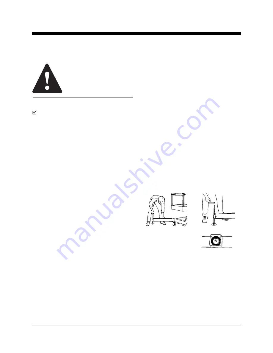
5 Install the outriggers and adjust to level the

machine and raise the base casters slightly off
the ground.

6 Check the interlock

display. Be sure all four
interlock display lights are
on and all four outriggers
are in firm contact with the ground.

7 Use the bubble level to make sure the machine

is level.

Note: If adjustment is necessary, check the bubble
level and interlock display again to make sure the
machine is level and all four interlock display lights
are on.

Operating Instructions

Содержание AWP-15S

Страница 1: ......

Страница 2: ...rules and operating instructions before operating this machine Only trained and authorized personnel shall be permitted to operate this machine This manual should be considered a permanent part of you...

Страница 3: ...tand the safety rules before going on to the next section 2 Always perform a pre operation inspection 3 Always perform function tests prior to use 4 Inspect the workplace 5 Only use the machine as it...

Страница 4: ...tform or against any part of this machine Do not place or attach overhanging loads to any part of this machine Do not raise the platform unless the machine is level Do not set the machine up on a surf...

Страница 5: ...lower the platform and do not continue to operate the machine CE AUS Narrow or RT base models Indoor use only Do not raise the platform when wind speeds may exceed 0 mph 0 m s If wind speeds exceed 0...

Страница 6: ...Maintain a firm footing on the platform floor at all times Do not exit the platform while raised If a power failure occurs have ground personnel activate the manual lowering valve Keep the platform f...

Страница 7: ...ment of the machine on or near inclines Stay clear of descending platform Improper Use Hazard Do not leave the machine unattended unless the key is removed to secure from unauthorized use Bodily Injur...

Страница 8: ...azards Batteries emit explosive gas Keep sparks flames and lighted tobacco away from the battery Charge the battery in a well ventilatedarea Do not disconnect charger DC output wires from the battery...

Страница 9: ...tly hazardous situation which if not avoided will result in death or serious injury Orange used to indicate the presence of a potentially hazardous situation which if not avoided could result in death...

Страница 10: ...h 3 Outrigger interlock display lights four 4 Low battery indicator light for auxiliarylowering 5 DC models Low battery indicator light 6 Powerlight 7 Auxiliaryplatformlowering button 8 Airpressuregau...

Страница 11: ...ocket 18 Manuallowering valve under machine 19 Airlinelubricator adjustmentknob 20 Air supply for machine 21 Airlinelubricator 22 DC models Battery pack with charger 23 Hydraulicpowerunit 24 Winching...

Страница 12: ...Pre operationInspectionandroutinemaintenance The Pre operation Inspection is a visual inspection performed by the operator prior to each work shift The inspection is designed to discover if anything i...

Страница 13: ...er drip rate Adjust as needed See Maintenance section Air models Check the air filter regulator canister Drain water as needed See Maintenancesection Check the following components or areas for damage...

Страница 14: ...to performthisprocedure Indicates that new parts will be required to perform this procedure Check the Battery DC Models Proper battery condition is essential to good machineperformanceandsafeoperatio...

Страница 15: ...ntial to maintain proper pressure in all air filled tires Improperly inflated tires can affect machinehandling 1 Check each tire with an air pressure gauge Add air as needed The proper air pressure is...

Страница 16: ...drip rate is achieved Check the Air Filter Regulator Canister Air Models It is essential to drain the air filter regulator canister of water to ensure good air motor performance and service life A wa...

Страница 17: ...orkplace 5 Only use the machine as it was intended Fundamentals The Function Tests are designed to discover any malfunctions before the machine is put into service The operator must follow the step by...

Страница 18: ...air pressuregaugeshould read 80 110 psi 5 5 7 8 bar 6 Select an outrigger and slide it into a base socket until the outrigger lock pin snaps into place Adjust the outrigger to level the machine and r...

Страница 19: ...ck to the previous setting and check the bubble level 18 Repeat this procedure for each outrigger Test Auxiliary Platform Lowering AC DC Models 19 Raise the platform slightly 20 Disconnect the power s...

Страница 20: ...Inspection helps the operator determine if the work place is suitable for safe machine operation It should be performed by the operator prior to moving the machine to the work place It is the operato...

Страница 21: ...achine directly below the desired workarea 2 Connect to the appropriate power source DC models Connect battery pack AC models Connect to a grounded 15A AC power supply Use a 12 gauge 3 3mm2 3 wire gro...

Страница 22: ...E a control activate button b up down switch Manual Lowering 1 Activate the manual lowering valve located at the bottom of the hydraulic cylinder Auxiliary Platform Lowering AC DC Models 1 Turn the ke...

Страница 23: ...the AUTO position 8 Monitor the ampere meter for the correct charge rate The initial charge rate should be approximately 10A The charge rate will decrease as the battery reaches full charge 9 The cha...

Страница 24: ...y is being performed i e slippery icy raining The appropriate number of people and proper lifting techniques must be used to prevent physical injury Transport Instructions Observe and Obey Be sure the...

Страница 25: ...PERATINGINSTRUCTIONS a b a b 7 Hook the loading pivot to the stop bracket 8 Position the machine flush against the loadingsurface Lower and lock the stop bracket to the lowest lock pin position above...

Страница 26: ...ine for loose or unsecured items 5 Connect the cable to the winching point located at the rear of the base 6 Carefully winch the machine onto the truck 7 Secure the machine base and mast to the transp...

Страница 27: ...0S models and optional on standard base AWP 15S 20S 25S and 30S models The tilt back frame is not available on narrow base machines or rough terrain base machines Lifting Instructions The number of pe...

Страница 28: ...a firm grasp on the tilt back frame and removethe retainingpin 4 Lower the tilt back frame and guide the tilt back strut into the strut socket 5 Insert the retaining pin into the strut socket Tilting...

Страница 29: ...he machine rests at mid tilt position 4 Lower the machine with the T handle until the base casters are in contact with the ground Use the appropriate number of people and proper lifting techniques 5 R...

Страница 30: ...31245 Warning Collision Hazard 1 33550 Safety Tape CE 37133 Label Interlock Display 1 37141 Notice Manual Lowering Instructions 1 37142 Notice Operating Instructions 1 37143 Notice Max Capacity 300 l...

Страница 31: ...Super Series 29 Operator sManual First Edition Ninth Printing or 1257853 or 1257854 or 1260610 or 46211 DECALS Models without Tilt back Frame Note Platform decals may be in diffferent locations on opt...

Страница 32: ...ies Part No 37168 Operator sManual First Edition Ninth Printing or 1257853 or 1257854 or 1260610 or 46211 DECALS Models with Tilt back Frame Note Platform decals may be in diffferent locations on opti...

Страница 33: ...ed Standard Base Specifications Machine weight DC AC models AWP 15S 718 628 lbs 326 285 kg AWP 20S 767 677 lbs 348 307 kg AWP 25S 817 727 lbs 371 330 kg AWP 30S 867 777 lbs 393 352 kg AWP 36S 1107 101...

Страница 34: ...orner access wall access 211 2 121 4 in 30 163 4 in 321 2 17 in CE Outdoor 54 6 30 8 cm 76 42 4 cm 82 5 43 4 cm AWP 30S AWP 36S AWP 40S Outrigger footprint 691 4 x 611 4 in 831 4 x 751 4 in 89 x 81 in...

Страница 35: ...x 20 x 443 4 in l x w x h 66 cm x 51 cm x 1 1 m Narrow fiberglass platform 26 x 22 x 431 2 in l x w x h 66 cm x 56 cm x 1 1 m Outrigger Specifications Narrow Base AWP 15S AWP 20S AWP 25S AWP 30S Outr...

Страница 36: ...4 ft 9 in 7 6 m AWP 30S 29 ft 6 in 9 0 m Lift capacity AWP 15S 20S 25S 350 lbs 30S models except Canada 159 kg Lift capacity 300 lbs models sold in Canada only 136 kg Power source DC model 12V AC mode...

Страница 37: ......

Отзывы: