Testing Cell For Bad Contacts
1. Remove the cover and power box cover panel.
2. The cell must be in the Air Cleaner for this test.
3. Turn the Air Cleaner
ON
and defeat the safety
interlock switch.
4. Place a plastic handled screwdriver into the direction
arrow slot. Do not apply excessive force.
5. There should be an initial snap when the plates are
shorted, then no sound. If a hissing occurs, then
there is a bad contact. Look along the top of the cell,
with the short still in place. If there is a small arc
between the cell top and copper contact, then that is
the bad contact. Pull the cell out and gently pull the
copper contact down.
6. If an arc is not seen and there is a bad contact, then
the problem may be an internal contact in the cell.
See below for additional testing.
Testing Cell With An Ohmmeter
To test the cell for a dead short or a bad contact an
ohmmeter can be used.
Always discharge the cell with
a screw driver before testing with an ohmmeter.
1. With the ohmmeter set on its lowest scale take a
reading between the top center contact of the cell and
the ionizing fingers on the bottom of the cell. You
should have continuity. If you do not then there is a
bad contact between the center contact and the top
set of ionizing fingers.
2. Test the resistance between the top center contact
and the cell frame. You should read infinite
resistance. If not you have a short in the ionizing
section.
3. Take a reading between the two outside contacts on
the top of the cell. You should have continuity. If you
do not then there is a bad contact between one of the
contacts to the live cell plate. Test each top outside
contact to the last plate in the cell to determine which
contact is not mating properly.
4. Test the resistance between the outside contacts and
the cell frame. You should read infinite resistance. If
not you have a short in the collecting section.
Replacing A Tungsten Ionizing Wire
Replacement wires are cut to the correct length and
have eyelets at each end for easy replacement.
1. Turn
OFF
power to Air Cleaner.
2. Remove cell from Air Cleaner.
3. Remove all parts of broken wire from the cell. If
necessary, the cell may be used temporarily with one
wire missing until a replacement is received.
4. Place one end of the loop over the finger at the
bottom of the cell.
5. Using needle-nose pliers, grip the other end of wire,
near the bottom of the top loop. Pull the wire up
toward the top finger. As you apply tension, the
bottom finger will give, allowing the placement of the
loop around the top finger.
6. Install cell in Air Cleaner.
7. Return power to Air Cleaner.
8. Test cell for proper operation.
Replacing A Fan Motor
1. Turn
OFF
power to Air Cleaner at the source.
2. Open the cover and remove cells and prefilters from
Air Cleaner.
3. Remove the fan blade from the motor shaft.
4. Remove the cover and power box cover panel.
Disconnect the four motor wires from the terminal
block. Gently pull the wires up into the motor
compartment.
5. Remove the four hex nuts holding the motor plate to
the cabinet. Remove the motor and plate.
6. Remove the four hex nuts from the back of the motor
plate to release the motor.
7. Replace the isolator rubbers on the motor plate.
8. Attach the new motor to the motor plate with a flat
washer on both sides of the rubber isolator. Place the
motor plate into the cabinet with the wires toward the
plastic bushing to allow the wires to be feed to the
power box.
9. Secure the motor plate to the cabinet.
10. Feed the motor wires down through the plastic
bushing and secure to the terminal block.
#3 - White
#4 - Red
#5 - Yellow
#6 - Black
The white wire on units with a remote switch control
use a wire nut instead of terminal #3.
11. Reinstall the fan blade, cell and prefilter.
12. Replace the power box cover panel and close the
cover.
13. Turn
ON
the Air Cleaner and test the motor on all
speeds.
REMOTE SWITCH CONTROL
The remote switch control, if ordered with the unit,
has two switches which control power to the unit and
control the speed of the motor. The remote switch control
cannot be added to a non-remote unit.
The switch control can be mounted in a convenient
location and wired back to the unit to control the
functions. The control box has holes on the back for
mounting and knockouts on five sides for the electrical
wires to be attached. A terminal block is mounted inside
the box to facilitate wiring.
Run an approved seven wire cable between the
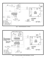
control box and the unit. Refer to Fig. 6 for wiring
connections between the control and the unit. Both the
remote box and the unit must be grounded for proper and
safe operation.
7


