6. Replace the hex nuts removed in Step 3. Ensure the
star washer is in place over the nut at the ground
location under the power board. For proper grounding
the washer must be located under the power board.
7. Reconnect wiring to neon lamp, HV1, HV2, and 24 V
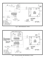
terminals on the new power board. See Fig. 5.
8. Return power to Air Cleaner. Test power board.
9. Replace power box cover panel and close cover.
Note:
The power board has been set before shipping. It
is not usually necessary to reset the voltage to the new
load. If you do need to adjust the voltage refer to Setting
Voltage of Power Board section for more information.
Testing The 24 V Transformer
1. Remove the cover and cover panel to the power box.
2. Disconnect the leads of the 24 V transformer from the
power board. See Fig. 5. Do not short the leads.
3. Push a screwdriver into the slot to defeat the interlock
switch and turn the Air Cleaner
ON
.
4. Measure the voltage across the leads with a
voltmeter. Voltage should read 25 - 28 VAC.
5. If no voltage is present, check the voltage from the
system switch.
6. If there is voltage to the transformer but no output,
replace the transformer.
Replacing The 24 V Transformer
Before replacing the transformer, check the
resistance across the power board 24 V input terminals,
without the transformer connected. Resistance should
read above 20K ohms with an analog meter and above
4M ohms with a digital meter. If the resistance readings
are below these values, the power board may be the
cause of the transformer failure.
Before replacing the 24 V transformer, turn
OFF
the
power to the Air Cleaner at the source.
1. Remove the cover and power box cover panel.
2. Disconnect the secondary leads from the transformer
to the 24 V terminals on the power board. See Fig. 5.
3. Remove the black primary lead from the system
switch. Remove the wire nut from the other primary
lead.
4. Remove the 2 hex head nuts and washers from the
transformer studs.
5. Remove the transformer.
6. Place new transformer over studs and re-install the
hex head nuts and washers to secure into place.
7. Connect the secondary leads (white) to the 24 V
terminals on the power board (P1 & P2).
8. Place one black lead on the system switch terminal.
9. Place the other black lead with the two white leads
from the terminal block and connect with the wire nut
you removed earlier.
10. Replace power box cover panel and close cover.
11. Turn
ON
the power to the Air Cleaner and test.
Setting Voltage Of Power Board
Voltage on the power board may drop below required
level when the installation area is too damp, too cold or
the input power to the unit is low. Voltage on power board
may be too high when the installation area is too dry or
too hot or the input power to the unit is high. By adjusting
the HV Adj. potentiometer, the voltage can be set to
optimum level. A high voltage meter capable of
measuring 10,000 VDC is required. To test and adjust
voltage level, perform the following procedure:
1. Turn the Air Cleaner
ON
and wait 5 minutes before
checking voltage to allow voltage on cell to stabilize.
2. Turn the Air Cleaner
OFF
, with the cell in the unit.
3. Remove cover and the power box cover panel.
4. Connect the ground of the high voltage meter to the
ground stud in the power box.
5. Turn the Air Cleaner
ON
and defeat interlock switch.
6. Measure the voltage at HV1 and HV2 on the power
board.
7. Adjust the HV Adj. potentiometer until the voltage
reading matches the voltage in Fig. 5. Adjusting the
potentiometer
clockwise decreases
the voltage and
turning
counter-clockwise increases
the voltage.
8. Turn
OFF
the Air Cleaner.
9. Remove the high voltage meter.
10. Replace the power box cover panel and close cover.
11. Turn
ON
the Air Cleaner.
Setting Approximate Voltage Without High Voltage
Meter
A high voltage meter should be used to set the high
voltage. If one is not available, this method can be used.
This will only set an approximate voltage. After using this
method, the voltage should be reset with a high voltage
meter as soon as possible.
1. Remove power box cover panel, with the cell in the
unit.
2. Turn the HV Adj. potentiometer fully counter-
clockwise. The Air Cleaner may arc or snap at this
point.
3. Turn the HV Adj. potentiometer clockwise
approximately a quarter turn.
4. Replace power box cover panel and close cover.
Testing For Voltage At The Cell
1. Remove the cover and power box cover panel.
2. The cell must be in the Air Cleaner for this test.
3. Turn the Air Cleaner
ON
and defeat the safety
interlock switch.
4. Place a plastic handled screwdriver into the direction
arrow slot. Do not apply excessive force.
5. If there is a good snap then there is high voltage at
the cell.
6


