


BASIC ADJUSTMENTS AND CONTROLS
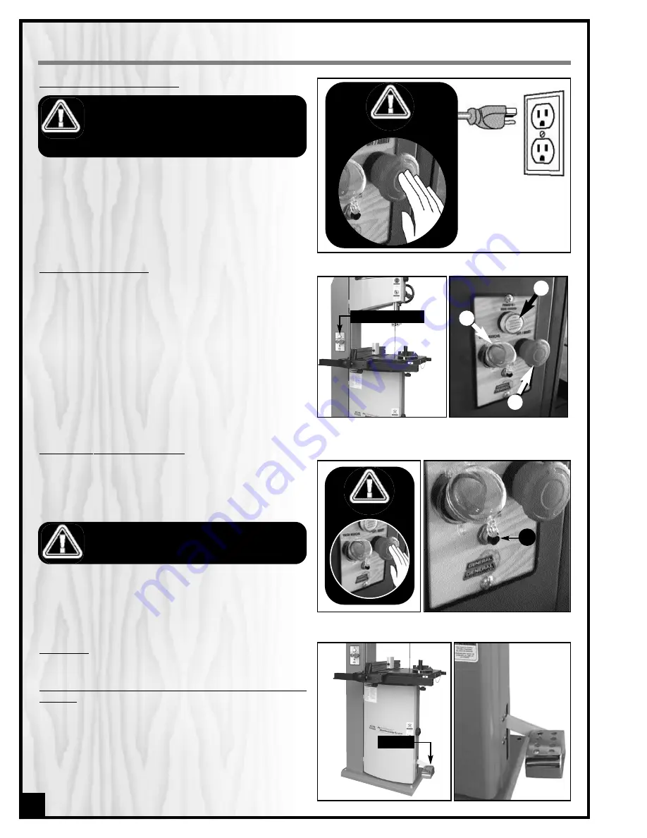
CONNECTING TO A POWER SOURCE
MAGNETIC SAFETY SWITCH
This model 90-170B is equipped with a MAGNETIC SAFETY
SWITCH located at the front, on the frame of the machine.
This magnetic switch is designed to protect the unit and the
user from power surges, power outages and unwanted or
unintentional start-up.
The switch assembly is equipped with a GREEN “ON” button
with protective cap
B
to prevent unwanted or unintention-
al start-up, and a RED spring loaded “OFF” button
C
. Once
the RED “OFF” button has been pressed, the machine can
only be started by turning the RED button to the right to
release the stop button it.
When you have finished using the machine be sure to unplug
the bandsaw from the power source.
TO REDUCE THE RISK OF SHOCK OR FIRE DO NOT OPER-
ATE THE UNIT WITH A DAMAGED POWER CORD OR PLUG.
REPLACE DAMAGED CORD OR PLUG IMMEDIATELY.
TO AVOID UNEXPECTED OR UNINTENTIONAL START-UP,
MAKE SURE THAT THE POWER SWITCH IS IN THE OFF POSI-
TION BEFORE CONNECTING TO A POWER SOURCE.
Refer back to the section entitled “ELECTRICAL REQUI-
REMENTS” and make sure all requirements and ground-
ing instructions are followed.
Once the assembly has been completed, plug the
power cord into an appropriate outlet. The “POWER IN”
indicator light
A
will illuminate.
FOOT BRAKE
This bandsaw is also equipped with a FOOT BRAKE locat-
ed at the bottom of the machine. This device allows for
immediate immobilization of the blade and machine
shut off.
Notice – The foot brake is not designed to function as the pri-
mary stop mechanism of this saw. The foot brake should be
used for emergency situations or any time it is necessary to
immobilize the blade quicker than normal. Under normal
working conditions the red stop button should be used as the
primary stop mechanism. Continuously using the foot brake
as the primary stop mechanism will lead to premature wear
of the brake and may cause damage to the motor.
12
THERMAL RELAY / CIRCUIT BREAKER
TO AVOID UNEXPECTED OR UNINTENTIONAL START-UP BE
CERTAIN THAT THE POWER SWITCH HAS BEEN SET TO THE
OFF POSITION BEFORE RE-SETTING THE THERMAL RELAY.
To reset the thermal relay after it has been tripped: set the
power switch to the “off” position and press the thermal
relay re-set button
D
, then restart the machine.
The unit is equipped with a thermal relay (circuit breaker)
D
located under the magnetic switch, to protect the motor
from power surges or spikes in line voltage. In the event of a
power surge, the thermal relay will be automatically tripped
thereby cutting off the power to the motor.
SWITCH OFF
MAGNETIC SAFETY SWITCH
FOOT BRAKE
SWITCH OFF
B
A
C
D
Содержание 90-170B M1
Страница 31: ...WIRING DIAGRAM 31...