FL4000
vii
Quick Start Guide
Mounting and Wiring the Detector
Pay special attention to the conduit seal entry (Canadian Electrical Code Handbook Part 1,
Section 18-154). Mount the detector by using the swivel mount or mounting bracket hardware.
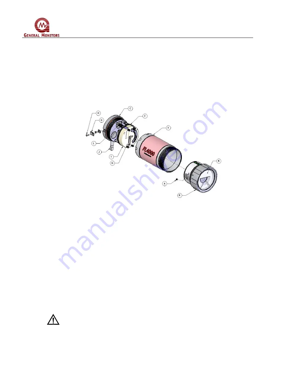
The following procedure should be used in conjunction with the housing diagram below to
disassemble the Electronic Module Tube for wiring:
Figure 1: FL4000 Housing
1. Loosen the Setscrew (A) located on the Compression Cap (B) and unscrew the
Compression Cap (B) until Optical Module Assembly is completely removed.
2. Loosen Captive Screw (H) located on the left side of the Junction Module Base (C),
DO
NOT REMOVE IT COMPLETELY.
Lift and turn the Bracket Top Lock (D) ¼ turn clockwise
to unlock.
3. Unscrew the Electronic Module Tube (E) approximately 9 turns. Remove and store in a
safe area.
4. Unscrew Knurled Nuts (L).
5. Remove the Field Wiring Board assembly (F) by grasping it by the PCB Wiring Protector at
the rear of the assembly (G) and gently pulling it forward,
DO NOT PULL ON THE ENTRY
CUP (I) TO REMOVE THE ASSEMBLY, DAMAGE COULD OCCUR.
The Field Wiring
Board assembly is connected to the Junction Module Base with a lanyard to prevent the
unit from falling during the wiring process.
6. Wire the unit to the site-wiring following the connection diagram shown in Figure 5.
7. Reassemble the unit using steps 1 thru 4 in reverse.
CAUTION:
Do not unscrew the Electronic Module Tube without first removing the Optical
Module Assembly. Unscrewing the Tube from the Junction Module Base while
the Optical Module Assembly is attached will invariably damage the unit.
Содержание FL4000
Страница 2: ...ii FL4000 This page intentionally left blank ...
Страница 8: ...FL4000 viii Figure 2 Mounting Instruction Figure 3 Wall Mounting Assembly ...
Страница 24: ...FL4000 24 Figure 11 Horizontal FOV n Heptane Low Sensitivity Figure 12 Vertical FOV n Heptane High Sensitivity ...
Страница 60: ...FL4000 60 6 2 Final Assembly Figure 26 FL4000 Cross Section View ...


