FL4000
37
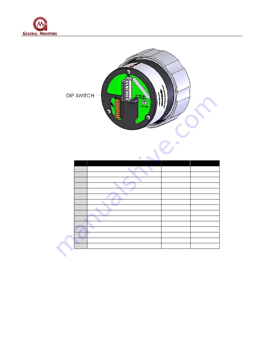
Figure 23: Dipswitch Location
Table 21: Dipswitch Options
#
Option
On/Closed
Off/Open
1
High Sensitivity
1 and 2
2 Medium
Sensitivity
1
2
3 Low
Sensitivity
2
1
4
0-Second Alarm Time Delay
3 and 4
5
8-Second Alarm Time Delay
4
3
6
10-Second Alarm Time Delay
3 and 4
7
14-Second Alarm Time Delay
3
4
8 ALARM
Non-Latching
5
9 ALARM
Latching
5
10 WARN
Non-Latching
6
11 WARN
Latching
6
12
ALARM Normally Energized
7
13
ALARM Normally De-Energized
7
14
WARN Normally Energized
8
15
WARN Normally De-Energized
8
3.8 Powering of the FL4000
After connecting to a 24 VDC power source, the unit will go through a power up delay of
approximately 15 seconds. The LEDs will blink in alternating red – green sequence, the unit will
output an analog signal of 0mA (3.5 mA with HART) and the fault relay will be in the de-
energized state. If the unit is configured with relays energized, the relays will de-energize for
approximately 0.5 seconds. Upon completion of the power on sequence, the green LED will
alternate - on for 5 seconds and off for 0.5 seconds to indicate a READY status.
Содержание FL4000
Страница 2: ...ii FL4000 This page intentionally left blank ...
Страница 8: ...FL4000 viii Figure 2 Mounting Instruction Figure 3 Wall Mounting Assembly ...
Страница 24: ...FL4000 24 Figure 11 Horizontal FOV n Heptane Low Sensitivity Figure 12 Vertical FOV n Heptane High Sensitivity ...
Страница 60: ...FL4000 60 6 2 Final Assembly Figure 26 FL4000 Cross Section View ...


