Operation
4-16
CG-1220 DTR
4.2.5.6 SYSTEM
MEMORY
The SYSTEM MEMORY menu contains functions related to the storage of system
parameters in nonvolatile RAM (NVRAM).
FACTORY CALIBRATION
contains system parameters that are calibrated in
factory and are NOT normally changed by the user. CHANGING THE
PARAMETERS IN THIS MENU MAY DEGRADE THE PERFORMANCE OF THE
DTR.
SAMPLING FREQUENCY
compensates for the oscillator's slight deviation
from nominal 64 MHz. Entering the actual oscillator frequency to within
1Hz maximizes the receiver's performance. This calibration is done in the
factory for each DTR before shipment; it should NOT be changed in most
cases.
If it must be reconfigured, connect a cable from the 70 MHz IF monitor
(on the front of the DTR) to a spectrum analyzer. Set up the spectrum
analyzer as follows:
1) Set Auto Couple to ALL.
5) Center the frequency.
2) Set Frequency to 64 MHz.
6) Span down to 500 Hz.
3) Set Span to 5 KHz.
7) Record and enter the measured value.
4) Peak-search the signal.
NCO OFFSET
adjusts the frequency of the Numerically Controlled
Oscillator (NCO) on the SPU.
POWER LEVEL CALIBRATION
adjusts the calibration value used to
calculate the signal power measurement reported by the DTR (shown on
the front display in dBm). This parameter should NOT be modified under
normal circumstances.
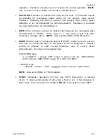
MANUAL IF OVERRIDE
allows the user to manually select the
Intermediate Frequency (IF) used by the L-band front end. The DTR
normally selects the optimal IF; this menu provides flexibility for special
cases.
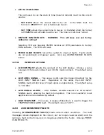
FREQUENCY #1-4 OVERRIDE
allows user selection of up to four IF1s
used by the L-band front end for current frequency. IF1 specifies an
approximate center for the digital filter within a 25 MHz analog filter
centered at 836.5 MHz. “Automatic” is the default setting, but
settings from 824.8 to 847.2 MHz are available.
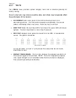
HARDWARE OPTIONS
allows factory setup of special hardware
configurations. These options are typically set in the factory and should
not be changed under normal circumstances.
POL INPUTS
allows user selection of STANDARD or MULTI PORT.
Содержание CG-1220
Страница 6: ...vi THIS PAGE INTENTIONALLY LEFT BLANK...
Страница 10: ...Table of Contents x THIS PAGE INTENTIONALLY LEFT BLANK...
Страница 16: ......
Страница 54: ...Maintenance 5 4 CG 1220 DTR THIS PAGE INTENTIONALLY LEFT BLANK...
Страница 56: ...Engineering Drawings 6 2 CG 1220 DTR THIS PAGE INTENTIONALLY LEFT BLANK...
Страница 59: ...Menu Tree APPENDIX B MENU TREE This Appendix contains the menu tree for the DTR CG 1220 DTR B 1...
Страница 65: ...Appendix C DTR Remote M C Protocol CG 6073 Rev R Jun 2012 4 THIS PAGE INTENTIONALLY LEFT BLANK...
Страница 129: ...Appendix C DTR Remote M C Protocol CG 6073 Rev R Jun 2012 68 THIS PAGE INTENTIONALLY LEFT BLANK...
Страница 130: ...Remote M C Protocol C 2 CG 1220 DTR THIS PAGE INTENTIONALLY LEFT BLANK...
Страница 133: ...Acronyms Abbreviations TX Transmit V Volts VAC Volts AC VDC Volts DC VSWR Voltage Standing Wave Ratio CG 1220 DTR D 3...
Страница 134: ...Acronyms Abbreviations D 4 CG 1220 DTR THIS PAGE INTENTIONALLY LEFT BLANK...


