Installation
3-12
CG-1220 DTR
3.5.1 Analog Voltage Output (DAC) Setup
1.
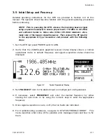
Tune frequency to obtain desired signal at maximum power level.
2.
Use DAC SETUP menu to establish VOLTAGE RANGE, MINIMUM REF POWER
LEVEL, and SLOPE.
DAC1 provides an analog DC voltage, proportional to signal level, on pins 1 and
14 (+OUT, -OUT) of I/O Interface #1 on the back panel.
A.
The DC VOLTAGE RANGE of the Digital to Analog Converter (DAC) is set to
the default range of (0 to +10V). For Special uses, the voltage range can
alternatively be set to (-10 to +10V), or (-5 to+5V).
B.
The SLOPE defaults to 0.3V/dB. SLOPE controls the rate of change of the DC
output voltage with respect to a 1 dB change in signal power level.
C.
The MINIMUM REF POWER LEVEL establishes the power level corresponding
to the minimum DAC voltage. The default is –90 dBm which emulates GDST
“TRL” operation.
3.
Check DAC1 output voltage (displayed on the front panel) and adjust MINIMUM
REF POWER LEVEL to obtain 8 VDC.
Note:
If both DAC1 and DAC2 are enabled, the front panel display will report DAC1 voltage real-
time (not at specified DAC1 update rate). If DAC1 is disabled and DAC2 is enabled, front display
will report DAC2 voltage real-time; label will change to DAC2=. If DAC1 is enabled and DAC2 is
disabled, front display will report DAC1 voltage real-time. If DAC1 is disabled and DAC2 is
disabled, front display will not report anything (blank field).
3.5.2 Setting
up
Beacons for 7134 Remote Control
This brief summary outlines steps necessary to establish beacons which can be
accessed via remote control from GDST 7134 ACUs.
1.
Set necessary parameters such as FREQUENCY, SLOPE, etc. See Section
4.2.5.4, BEACON SETUP for a complete list of beacon parameters.
2.
Execute the STORE BEACON 1-4 menu at CONFIGS\BEACON-SETUP\STORE-
BEACONS. These current settings will be stored in the respective beacon
(BEACON 1-4).
3.
Test by recalling BEACON 1-4.
4.
The connection to the 7134 is via the I/O Interface #1. (Refer to Table 3-2)
5.
To allow the 7134 ACU to select beacons, set CONFIGS\REMOTE CONTROL to
I/O Interface #1.
Содержание CG-1220
Страница 6: ...vi THIS PAGE INTENTIONALLY LEFT BLANK...
Страница 10: ...Table of Contents x THIS PAGE INTENTIONALLY LEFT BLANK...
Страница 16: ......
Страница 54: ...Maintenance 5 4 CG 1220 DTR THIS PAGE INTENTIONALLY LEFT BLANK...
Страница 56: ...Engineering Drawings 6 2 CG 1220 DTR THIS PAGE INTENTIONALLY LEFT BLANK...
Страница 59: ...Menu Tree APPENDIX B MENU TREE This Appendix contains the menu tree for the DTR CG 1220 DTR B 1...
Страница 65: ...Appendix C DTR Remote M C Protocol CG 6073 Rev R Jun 2012 4 THIS PAGE INTENTIONALLY LEFT BLANK...
Страница 129: ...Appendix C DTR Remote M C Protocol CG 6073 Rev R Jun 2012 68 THIS PAGE INTENTIONALLY LEFT BLANK...
Страница 130: ...Remote M C Protocol C 2 CG 1220 DTR THIS PAGE INTENTIONALLY LEFT BLANK...
Страница 133: ...Acronyms Abbreviations TX Transmit V Volts VAC Volts AC VDC Volts DC VSWR Voltage Standing Wave Ratio CG 1220 DTR D 3...
Страница 134: ...Acronyms Abbreviations D 4 CG 1220 DTR THIS PAGE INTENTIONALLY LEFT BLANK...


