Introduction
1.2 Controls and Indicators
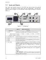
The controls and indicators located on the DTR front panel provide the normal
operator interface. The DTR front panel is shown in Figure 1-1 with its controls
and indicators identified. The function of each is detailed in Section 4, Operation.
1
3
2
4
5
6
7
Figure 1-1
DTR Front Panel
TABLE 1-1
CONTROLS AND INDICATORS
1. Receiver
Status
Display
2. Soft
Keys
3. Navigation
Keys
4. Status
Indicators
5. Numeric
Keypad
6. Spin
Knob
7. IF Monitor Port
1-3
Содержание CG-1220
Страница 6: ...vi THIS PAGE INTENTIONALLY LEFT BLANK...
Страница 10: ...Table of Contents x THIS PAGE INTENTIONALLY LEFT BLANK...
Страница 16: ......
Страница 54: ...Maintenance 5 4 CG 1220 DTR THIS PAGE INTENTIONALLY LEFT BLANK...
Страница 56: ...Engineering Drawings 6 2 CG 1220 DTR THIS PAGE INTENTIONALLY LEFT BLANK...
Страница 59: ...Menu Tree APPENDIX B MENU TREE This Appendix contains the menu tree for the DTR CG 1220 DTR B 1...
Страница 65: ...Appendix C DTR Remote M C Protocol CG 6073 Rev R Jun 2012 4 THIS PAGE INTENTIONALLY LEFT BLANK...
Страница 129: ...Appendix C DTR Remote M C Protocol CG 6073 Rev R Jun 2012 68 THIS PAGE INTENTIONALLY LEFT BLANK...
Страница 130: ...Remote M C Protocol C 2 CG 1220 DTR THIS PAGE INTENTIONALLY LEFT BLANK...
Страница 133: ...Acronyms Abbreviations TX Transmit V Volts VAC Volts AC VDC Volts DC VSWR Voltage Standing Wave Ratio CG 1220 DTR D 3...
Страница 134: ...Acronyms Abbreviations D 4 CG 1220 DTR THIS PAGE INTENTIONALLY LEFT BLANK...


