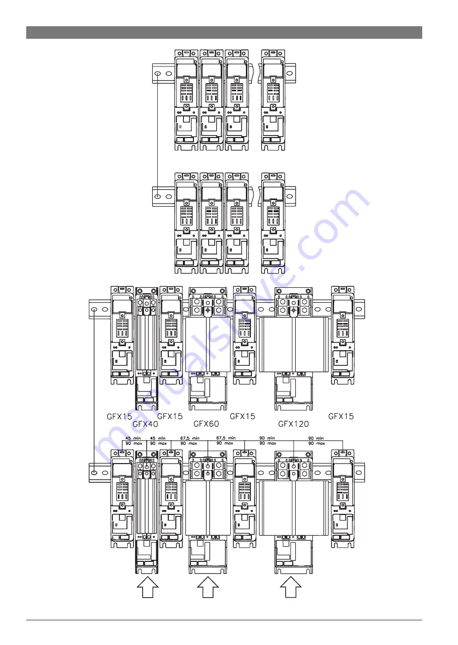
2.3 Connection examples
220 mm (MIN)
AIR FLOW
300 mm (MIN)
6
80346B_MHW_GFX-VALVOLE_0709_ENG
Страница 1: ...entiometer 14 8 Manual calibration of valve 14 9 Technical specifications 15 10 Technical Commercial information 16 10 1 Accessories 17 To distinguish between the type and importance of the information provided in these instructions for use graphic symbols have been used as a reference to make interpreting the information clearer Indicates the contents of the various manual sections the general wa...
Страница 2: ...he table below These details must always be kept close at hand and referred to the personnel involved in the event of help from Gefran Customer Service Assistance Check also that the controller is complete and has not been damaged at all during transit and that the package contains not only the controller and these Instructions for Use as well as for the GEFLEX Multifunction Master model the Progr...
Страница 3: ...c standards have been adopted as indicated in the table below BT Conformity low tension in accordance with Directive 2006 95 CE EMC conformity has been tested with the following connections table 1 Advice for Correct Installation for EMC Instrument power supply The power supply to the electronic equipment on the switchboards must always come directly from an isolation device with a fuse for the in...
Страница 4: ...utput cables 1 mm2 3 5 mt Serial connection wire 0 35 mm2 3 5 mt Power connection cable see related sections 3 5 mt Thermocouple input probe 0 8 mm2 compensated 5 mt PT100 temperature resistance input probe 1 mm2 3 mt EMC conformity has been tested with the following connections Table 1 Electrical device of measure control laboratory prescription electromagnetic compatibility Generic standards emi...
Страница 5: ...is present LO process variable value is di Lo S HI process variable value is di Hi S Sbr broken probe or input values beyond maximum limits Err third wire broken for Pt100 PTC or input values below minimum limits ex for CT with incorrect connection Led L1 Status LED green Freely settable with parameter 197 Ld St Default setting is16 RUN flashes Connection to previous module Slave and Expansion mod...
Страница 6: ...2 3 Connection examples 220 mm MIN AIR FLOW 300 mm MIN 6 80346B_MHW_GFX VALVOLE_0709_ENG ...
Страница 7: ...f the Geflex Slaves by setting parameter rL6 to 160 128 32 on each Geflex Slave For more information see the Configuration and Programming manual Geflex Master rL4 Geflex Slave rL6 Geflex Slave rL6 Geflex Master OUT4 Geflex Master rL3 Geflex Slave rL5 Geflex Slave rL5 Geflex Master OUT3 The OUT3 and OUT4 relays on the Geflex Master module provide special functions designed to reduce user wiring Th...
Страница 8: ... 4 AL2 OUT 3 AL1 OUT 2 COOL 1 2 3 4 5 6 7 8 7 5 4 2 1 J1 J2 3 4 Input Output Power Supply connections 1 2 3 4 5 IN o PE Potentiometer 1KΩ 100KΩ Amplified probe Voltage 0 10V d c Amplified probe Current 0 20mA d c J4 J5 J1 Probe and power supply terminal board J2 Relay output terminal board J3 Connection among modules J4 Power terminal board J5 Aux input terminal board 8 80346B_MHW_GFX VALVOLE_0709...
Страница 9: ...onnect a 220Ω 1 4W resistance between the RxD TxD P and RxD TxD N signals a 390Ω 1 4W resistance between the RxD TxD P and Vp signals and a 390Ω 1 4W resistance between the RxD TxD N and DGND signals at both ends of the Profibus network DeviceNet serial V CAN_L SHIELD CAN_H V 1 2 3 4 5 Connector 5 pin From DeviceNet network Shielded cable 2 pairs 22 24 AWG DeviceNet conformity We advise you to con...
Страница 10: ...able see order code with one of the following protocols ModBus Profibus or CANopen The following procedures are to be considered indispensable for the ModBus protocol For the other protocols refer to the specific Geflex Profibus and Geflex CANopen manuals GEFLEX modules are supplied preset for 19200 baud without parity and with rotary selector for node address 0 A maximum of ninety GEFLEX modules ...
Страница 11: ... Return the rotary selector on the Master module to the position assigned at point 3 The new node address parameter is saved permanently in each Geflex so you will not have to activate the AUTONODE sequence at future power ups Steps 1 4 5 8 and 11 are necessary only for Geflexes with firmware 1 0x In later versions when the rotary selector is moved the green STATUS LED remains on steadily for abou...
Страница 12: ... sequence at future power ups Steps 1 4 5 8 and 11 are necessary only for Geflexes with firmware 1 0x In later versions when the rotary selector is moved the green STATUS LED remains on steadily for about 6 seconds after which it resumes its normal operation saving the address 4 3 CHANGE sequence 4 4 Software On Off This function is obtained with the digital input if configured diG 6 All outputs c...
Страница 13: ... actuator time resolution 0 1 Represents the minimum change in position corresponding to a minimum change in power supplied by the instrument below which the actuator will not physically respond to the command This represents the minimum variation in position due to which the actuator does not physically respond to the command The minimum duration of the movement can be set in t on expressed as a ...
Страница 14: ... the difference between the position calculated by the controller and the only proportional component exceeds the value corresponding to the minimum impulse t_Lo the controller provides an OPEN or CLOSE command of the duration of the minimum impulse itself t_Lo At each delivery the integral component of the command is set to zero discharge of the integral The frequency and duration of the impulses...
Страница 15: ...C RTD 60mV 1V Ri 1MΩ 20mA Ri 50Ω Sampling time 120 msec J K R S T IEC 584 1 CEI EN 60584 1 60584 2 a custom linearization can be inserted 0 1 C DIN 43760 Pt100 JPT100 20Ω 0 2 f s 1 scale points at 25 C ambient temperature Potentiometer 1KΩ 0 2 10V Ri 100K 0 4 20mA Ri 50Ω Sampling time 240msec 24V 8mA Detection of short circuit or opening of probes LBA alarm HB alarm Configurable 1999 9999 Pid Auto...
Страница 16: ...IONAL MODULE 0 GFX M2 DIAGNOSTIC DIGITAL INPUT PNP Digital Input P 2 Relays RR AUXILIARY OUTPUTS P Master Valve RR Without functional module B_V With double relays modul V None 0 Multifunction input 0 4 20mA 0 10V IM Potentiometer input PO B_V M 0 0 COOLING OUTPUT Absent Logic 0 D Relays R Continuous output 0 10V 0 4 20mA C FUNCTIONAL MODULE 0 GFX S2 DIAGNOSTIC DIGITAL INPUT PNP Digital Input P Ab...
Страница 17: ... of terminals are available for installation on the Geflex heatsink or on DIN guide for installation on the faceplate Programming terminal for Geflex installation on DIN guide or on heatsink complete with connection cable to Geflex L 0 2 m GFX OP D Note see cable section for other cable lengths Programming terminal for Geflex installation on faceplate GFX OP P Note see cable section for connection...