


The controller determines, on the basis of the dynamics of the
process, the control output for the valve corresponding to the
opening of the same in such a way so as to maintain the
desired value of the process variable.
With counter-reaction valves the position is normally provided
by a potentiometer assembled on the actuator.
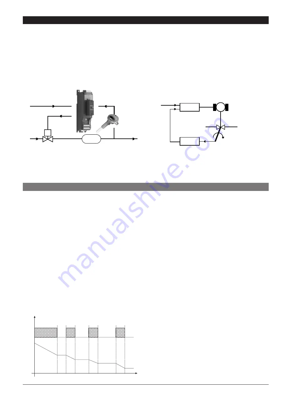
5 • ADJUSTMENT WITH MOTORIZED VALVE
Adjustment valve
Actuator
SetPoint
Process
M
CONTROL EXAMPLE FOR V0 VALVE
VALVE POSITION CONTROL
Control
Motor
Adjustment valve
Desired position
Process
variable
Valve position
feedback
potentiometer
In an adjustment process the adjustment valve has the
function of varying fuel delivery (frequently corresponding to
the thermal energy introduced into the process) in relation to
the signal coming from the controller.
For this purpose it is provided with an actuator able to modify
its opening value, overcoming the resistances produced by
the fluid passing inside it.
The adjustment valves vary the delivery in a modulated
manner, producing finite variations in the fluid passage inner
area corresponding to finite variations of the actuator input
signal, coming from the controller. The servomechanism, for
example, comprises an electric motor, a reducer and a
mechanical transmission system which actions the valve.
Various auxiliary components can be present such as the
mechanical and electrical safety end travels, manual actioning
systems, position location.
5.1 Characteristic parameters for valves control
- Actuator time (_At_) is the time employed by the valve to
pass from entirely open to entirely closed (or vice-versa), and
can be set with a resolution of one second.
It is a mechanical feature of the valve+actuator unit.
NOTE: if the actuator’s travel is mechanically limited it is
necessary to proportionally reduce the _At_ value.
- Minimum impulse (t_Lo) expressed as a % of the actuator
time (resolution 0.1%).
Represents the minimum change in position corresponding to
a minimum change in power supplied by the instrument below
which the actuator will not physically respond to the
command.
This represents the minimum variation in position due to
which the actuator does not physically respond to the
command.
The minimum duration of the movement can be set in t.on,
expressed as a % of actuator time.
- Impulsive intervention threshold (t_Hi) expressed as a % of
the actuator time (resolution 0.1%) represents the position
displacement (requested position – real position) due to which
the manoeuvre request becomes impulsive.
You can choose between 2 types of control:
1) ON time of movement = t.on and OFF time proportional to
shift and greater than or equal to t_Lo (we recommend setting
t.on = t.Lo) (set t.off = 0).
2) ON time of movement = t.on and OFF time = t.off. A value
set for t.off < t.on is forced to t.on. To activate this type, set
t.off < > 0.
The type of movement approach allows fine control of the
reverse drive valve (from potentiometer or not), especially
useful in cases of high mechanical inertia.
Set t_Hi = 0 to exclude modulation in positioning.
This type of modulated approach allows precise control of the
feedback actioned valve, by a potentiometer or not, and is
especially useful in cases of high mechanical inertia. Setting
t_Hi = 0 excludes modulation in positioning.
- Dead zone(_db_) is a displacement band between the
adjustment setpoint and the process variable within which the
controller does not supply any command to the valve (Open =
OFF; Close = OFF).
It is expressed as a percentage of the bottom scale and is
symmetrical with respect to the setpoint.
The dead zone is useful in an operative process to avoid
straining the actuator with repeated commands and an
insignificant effect on the adjustment. Setting _db_ = 0 the
dead zone is excluded.
t_Hi
t_Lo
t_Lo
t_Lo
t0
t1
t2
Graph of behavior inside the band with integral
time ¤ 0.
With integral time = 0, movement ON time is
always equal to OFF time.
t0 = t_Lo
13
80346B_MHW_GFX-VALVOLE_0709_ENG