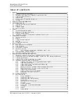
TABLE OF FIGURES
fig. 1
CE mark
15
fig. 2
Designation of the lifting points
21
fig. 3
Stopper with shackle
22
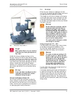
fig. 4
Transportation with a wire rope hoist
22
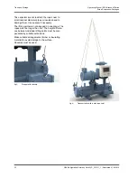
fig. 5
transportation using crossbeam
23
fig. 6
Location of the product identification (type plate)
33
fig. 7
Type plate
33
fig. 8
Safety labels of the pressure and temperature sensors, heater
34
fig. 9
Label of the safety valve
34
fig. 10
Labels of the screwed connections
34
fig. 11
Labels of the pipelines
35
fig. 12
Marking the direction of rotation of the compressor drive motor
35
fig. 13
Marking the direction of rotation of the oil pump motor
35
fig. 14
Labels of the pressure gauge
36
fig. 15
Test verification for the control system
36
fig. 16
Designation of the earth connection
37
fig. 17
Process flow diagram Grasso SP1, M-series
37
fig. 18
Main components of the GEA Grasso M-Series
38
fig. 19
GEA Grasso M-Series, arrangement of the SCP
39
fig. 20
GEA Grasso M-Series, arrangement of the compressor drive motor
39
fig. 21
GEA Grasso M-Series, arrangement of the coupling housing
40
fig. 22
GEA Grasso M-Series, arrangement of the oil separator
40
fig. 23
GEA Grasso M-Series, arrangement of the OMC block with oil filter system
41
fig. 24
GEA Grasso M-Series, arrangement of the oil cooler
41
fig. 25
GEA Grasso M-Series, arrangement of the (optional) oil pump
42
fig. 26
GEA Grasso M-Series, suction filter - check valve combination
42
fig. 27
GEA Grasso M-Series, arrangement of the controller
43
fig. 28
Corrosion resistance in presence of chlorides
51
fig. 29
Vacuum required to remove moisture from refrigerating plants
56
fig. 30
Stop valve open
57
fig. 31
Stop valve closed
57
fig. 32
Check valve
57
fig. 33
Shuttable check valve
57
fig. 34
Control valve
58
fig. 35
Shuttable check valve
58
fig. 36
Solenoid valve
58
fig. 37
Change-over valve
58
fig. 38
Oil pressure control valve
58
fig. 39
Overflow valve, safety valve
59
fig. 40
Pressure controlled check valve
59
fig. 41
Quick acting valve, spring-loaded
59
fig. 42
Charging valve, drain valve
59
fig. 43
Service valve
59
fig. 44
Oil temperature limiter
60
fig. 45
Temperature controlled control valve
60
fig. 46
Motor direction of rotation
62
fig. 47
Arrangement of MIN / MAX sight glasses
78
fig. 48
Operating position of the fine oil separation cartridges
79
Operating Manual | GEA Grasso M-Series
Screw Compressor Packages
GEA Refrigeration Germany GmbH | P_261511_1 | Generated 01.04.2015
9
Содержание Grasso M-Series
Страница 88: ......


