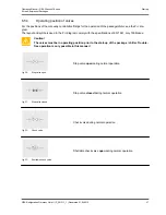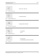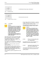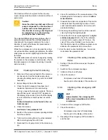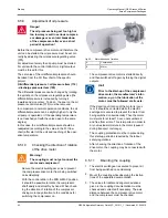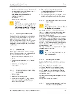
–
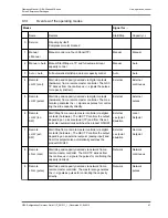
Danger!
Solid mounting of the coupling protec-
tion must be checked. Start-up must
not be carried out with the coupling
protection mounted.
–
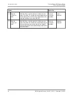
Check the protective gas filling (a positive pres-
sure ≥ 0.2 bar must be present)
Hint!
If defects are found, notify GEA Refrig-
eration Germany GmbH Service and
proceed according to their instruc-
tions.
8.2
Basics
The compressor must only be switched on if the
screw compressor package has been correctly con-
nected and filled with operating materials.
The activities described in this "Start-up" chapter
must be carried out in the prescribed sequence.
The screw compressor package is operated via the
terminal of the control unit.
After the target values have been entered, both auto-
matic and manual operation are possible.
The software of the control device and operation via
the terminal are described separately in the operat-
ing manual for the control system.
8.3
Connecting the screw compressor
package
Caution!
All mechanical connections must be
made according to the R+I diagram
which is valid for the project. The R+I
diagram is part of the product docu-
mentation.
Caution!
All electrical connections must be
made according to the circuit diagram
which is valid for the project. The cir-
cuit diagram is part of the product
documentation.
Check that components which have been removed
for transport, separately delivered components and
components provided by the customer are firmly
attached.
Check that all locating bolts are tight.
8.3.1
Connecting the pipes
The nitrogen filling of the screw compressor package
must be purged by opening the vent valves before
the connection of the pipes.
Establish all pipe connections so that the transmis-
sion of thermal expansion and vibration to the screw
compressor package is limited as far as possible.
Bellows-type expansion joints made of steel, or flexi-
ble metal hoses can be used for refrigerant and oil
lines, bellows-type expansion joints made from rub-
ber can be used for water connections.
Provide all pipe connections directly at the unit with
fixed points.
•
Connection of:
–
Suction line
–
Pressure line
–
Oil cooler water connection
•
If units are equipped with a safety valve: Con-
nect safety valve to the blow-off line.
•
Integrate relief valve in the suction line.
•
if units are equipped with a refrigerant cooled oil
cooler:
–
Connect the refrigerant feed line from h.p.
receiver (note geodetic height above oil
cooler).
–
Connect the evaporated refrigerant line to
the condenser
•
If refrigerant injection is used: Connect the refrig-
erant feed line from condenser or h.p. receiver
•
If an economiser is used: Connection the suction
line of the economiser to the charge connection.
Start-up
Operating Manual | GEA Grasso M-Series
Screw Compressor Packages
54
GEA Refrigeration Germany GmbH | P_261511_1 | Generated 01.04.2015
Содержание Grasso M-Series
Страница 88: ......

