background image

Hint!

Watch pressure and temperature!

the supporting, hanging and storage facilities are
misused.

control and regulation units including control sys-
tem software are tampered with.

the driving power generated by the motor is used
for purposes other than the operation of the
respective compressors and pumps.

1.6

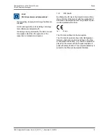
CE mark

By affixing the CE mark, the manufacturer confirms
the conformity of the product with the applicable EC
Directives and compliance with the principle require-
ments stipulated within them.

fig.1:

CE mark

The CE mark is affixed to the nameplate.
The CE mark for products from GEA Refrigeration
Germany GmbH is provided as defined in the Pres-
sure Equipment Directive, i.e. pressure equipment is
placed on the market with the required equipment
parts with safety function. This complete assembly is
subject to the Pressure Equipment Directive.

Operating Manual | GEA Grasso M-Series
Screw Compressor Packages

Basics

GEA Refrigeration Germany GmbH | P_261511_1 | Generated 01.04.2015

15

Содержание Grasso M-Series

Страница 1: ...Screw Compressor Packages GEA Grasso M Series Operating Manual Translation of the original text P_261511_1 ...

Страница 2: ...here the product is used the recognised technical regulations for safe and professional work must also be observed These operating instructions are part of the unit The entire documentation comprises these operating instructions and all additional operating instructions supplied with the unit It must be kept readily availa ble where the unit is installed The entire documenta tion must also be forw...

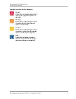
Страница 3: ...physical injuries or to the death Caution Stands for a possibly dangerous situa tion which could lead to light physical injuries or to damages to property Hint Stands for an important tip whose attention is important for the designa ted use and function of the device Operating Manual GEA Grasso M Series Screw Compressor Packages GEA Refrigeration Germany GmbH P_261511_1 Generated 01 04 2015 3 ...

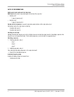
Страница 4: ... Handling instructions require you to do something Several consecutive steps result in a handling sequence that should be run in the specified order The handling sequence can be divided into separate steps Handling sequence 1 Handling sequence step 1 step 1 step 2 step 3 2 Handling sequence step 2 The subsequent handling sequence is the expected result Result of the handling sequence Individual ha...

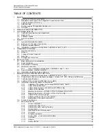
Страница 5: ...N AND FUNCTION 29 7 1 Installation in explosive atmospheres installation zones 1 und 2 29 7 2 Product code of screw compressor packages Grasso SP1 SP2 SPduo and M Series 30 7 3 Technical specifications 32 7 4 Location of the product identification name plate 33 7 5 Information and safety labels on the product 34 7 5 1 Labelling of the pressure and temperature sensors heater 34 7 5 2 Label of the s...

Страница 6: ...fault monitoring 61 8 5 7 Checking of the safety pressure limiter 61 8 5 8 Checking of the emergency OFF button 61 8 5 9 Adjustment of oil pressure 62 8 5 10 Checking the direction of rotation of the drive motor 62 8 5 11 Mounting the coupling 62 8 5 12 Checking the water circuits 63 8 5 13 Initial start up 63 8 5 14 Checking the adjustment of the control slide 63 8 5 15 Checking the control slide...

Страница 7: ...igerant side leak test 79 10 4 4 12 Venting the refrigerant circuit 80 10 4 4 13 Refrigerant evacuation 80 10 4 4 14 Checking the bearing noise 81 10 4 4 15 Checking the solenoid valves for capacity control 81 10 4 4 16 Checking the oil heater 81 10 4 4 17 Maintenance of the compressor drive motor 81 10 4 4 18 Checking the start regime 81 10 4 4 19 Checking the safety devices 81 10 4 4 20 Checking...

Страница 8: ...Operating Manual GEA Grasso M Series Screw Compressor Packages 8 GEA Refrigeration Germany GmbH P_261511_1 Generated 01 04 2015 ...

Страница 9: ... separator 40 fig 23 GEA Grasso M Series arrangement of the OMC block with oil filter system 41 fig 24 GEA Grasso M Series arrangement of the oil cooler 41 fig 25 GEA Grasso M Series arrangement of the optional oil pump 42 fig 26 GEA Grasso M Series suction filter check valve combination 42 fig 27 GEA Grasso M Series arrangement of the controller 43 fig 28 Corrosion resistance in presence of chlor...

Страница 10: ...Operating Manual GEA Grasso M Series Screw Compressor Packages 10 GEA Refrigeration Germany GmbH P_261511_1 Generated 01 04 2015 ...

Страница 11: ...vant technical regulations Technical personnel are representatives of the unit manufacturer and persons who as a result of their technical training experience and personal instruc tion in training measures have sufficient knowledge of applicable international and national standards applicable occupational safety regulations applicable accident prevention regulations applicable environmental protec...

Страница 12: ...quirements and environmental requirements Accident Prevention Regulation including implementation regulations BGR 500 chapter 2 35 on refrigeration plants heat pumps and cooling equipment BGV B3 regarding noise EN 12284 Refrigerant fittings safety related technical definitions testing and marking DIN 2405 Pipes in refrigeration plants marking VDMA specifications in particular VDMA 24 243 and 24 02...

Страница 13: ... instructions can lead to danger to personnel and the environment as well as damage to the unit Operating Manual GEA Grasso M Series Screw Compressor Packages Basics GEA Refrigeration Germany GmbH P_261511_1 Generated 01 04 2015 13 ...

Страница 14: ...ure equipment is not used according to the regula tions the safe use of the equipment is not guaran teed The supplier installer or the operator and not the manufacturer is responsible for all personal injury and damage to property resulting from improper use The pressure equipment is not designed for dynamic loads If there is a risk of lightning strikes the pres sure equipment must be earthed The ...

Страница 15: ...duct with the applicable EC Directives and compliance with the principle require ments stipulated within them fig 1 CE mark The CE mark is affixed to the nameplate The CE mark for products from GEA Refrigeration Germany GmbH is provided as defined in the Pres sure Equipment Directive i e pressure equipment is placed on the market with the required equipment parts with safety function This complete...

Страница 16: ...ns GEA Refrigeration Germany GmbH Factory Berlin Holzhauser Str 165 13509 Berlin Germany Tel 49 30 43592 600 Fax 49 30 43592 777 Web www gea com E Mail refrigeration gea com GEA Refrigeration Germany GmbH Factory Halle Berliner Straße 130 06258 Schkopau OT Döllnitz Germany Tel 49 345 78 236 0 Fax 49 345 78 236 14 Web www gea com E Mail refrigeration gea com Manufacturer Information Operating Manua...

Страница 17: ...f our products 3 2 Spare parts GEA Refrigeration Germany GmbH has its own prac tical and rapidly working spare parts department to supply the necessary spare parts worldwide Neces sary spare parts are shipped as quickly as possible In most cases you will receive your spare parts within 24 hours after placing the order You can contact us using the following hotlines Wireless out of hours 49 0 172 3...

Страница 18: ... feed cable must be laid for the operation of the package chiller The mains cable feed cable is to be specially protec ted and provided with an emergency stop switch 4 3 Possible residual hazards Warning Despite careful design of the machine and implementation of all the safety relevant regulations further risks for persons and machine during all life phases of the package chiller cannot be fully ...

Страница 19: ...oil level above the heating elements To this end a sepa rate oil level switch is used in each use case according to the necessary explosion protection specification Operation The same regulations apply in regard to the operat ing instructions for screw compressor packages in potentially explosive atmospheres as described in the applicable operating manual In addition to this the following extensio...

Страница 20: ...riginal spare parts may be used If original spares are not used the guarantee is invalidated or the owner is liable in the event of damage Each maintenance inspection see maintenance book must also include checking the secure fit of the threaded connections for the coupling safety hood Safety Operating Manual GEA Grasso M Series Screw Compressor Packages 20 GEA Refrigeration Germany GmbH P_261511_...

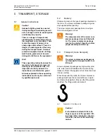
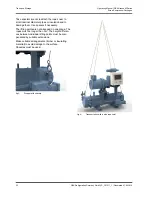
Страница 21: ...ackage is gener ally supplied without packing The screw compressor package has an inert gas filler in the refrigerant circuit Warning The compressor s of the screw com pressor package is are not filled with oil The screw compressor package must not be started therefore before proper assembly and start up 5 3 Transport crane transport Warning The screw compressor packages are not intended for trans...

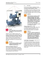
Страница 22: ...height differen ces between individual lifting points must be com pensated by suitable extensions Make suitable arrangements timber or insulating material to avoid damage to the surface Shackles must be used fig 3 Stopper with shackle fig 4 Transportation with a wire rope hoist Transport Storage Operating Manual GEA Grasso M Series Screw Compressor Packages 22 GEA Refrigeration Germany GmbH P_2615...

Страница 23: ...ed from jerks or impacts Warning Screw compressor packages must be adequately protected from external influences humidity frost extreme heat during storage This usually con cerns lengthy standing times outdoors before installation and start up of the refrigeration plant The manufacturer recommends the use of plastic sheet ing to cover the whole product The venting slits of the electric motors must...

Страница 24: ...ges that are equipped with a control 1 Storage temperature 10 C 2 Air humidity 50 If the screw compressor package is intended to be stored the following preparatory measures must be carried out ex works especially protection against internal and external corrosion All process connections on the screw compres sor package are sealed tight The screw compressor package is charged with dry gas to 1 bar...

Страница 25: ...technician of GEA Refrigera tion Germany GmbH is recommended Please pay attention to the information in the Start up chapter The general check includes changing the O ring on the compressor shaft seal as well as replacing the shaft seal of the oil pump Operating Manual GEA Grasso M Series Screw Compressor Packages Transport Storage GEA Refrigeration Germany GmbH P_261511_1 Generated 01 04 2015 25 ...

Страница 26: ...ers are used The welding seams must be inspected in accordance with the Pressure Equipment Directive after welding work by the customer or operator on pipe line con nections and flanges 6 2 Rigid installation The frame of the screw compressor unit liquid chiller is placed on foundation bolts on a prepared founda tion The frame must be levelled with suitable shims such that the coarse alignment rad...

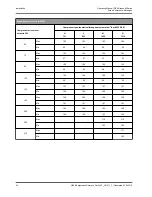
Страница 27: ...ture wetness is essential The manufacturer will not accept liability for damage due to incorrect outdoor installation 6 6 Information regarding noise emis sions The noise information provides approximate parame ters and apply to the installation without any secon dary noise protection measures The information has a tolerance of 3 dB The precise data depend closely on the emission values for the mo...

Страница 28: ...04 Min 97 97 97 97 90 Max 105 105 105 105 Min 98 98 98 98 110 Max 106 106 106 106 Min 99 99 99 99 132 Max 107 107 107 107 Min 100 100 100 100 160 Max 108 108 108 108 Min 101 101 101 101 200 Max 109 109 109 109 Min 102 102 102 102 250 Max 110 110 Min 103 103 315 Max 111 Min 103 Installation Operating Manual GEA Grasso M Series Screw Compressor Packages 28 GEA Refrigeration Germany GmbH P_261511_1 G...

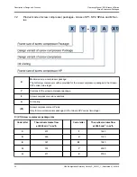
Страница 29: ... for pumping potentially explosive mixtures This means when the compressor is in intake condition the pumped liquid must not contain any oxygen The intake condition always refers to pressure layers in the overpressure range The owner operator and the system builder must use monitoring devices reflecting the respective state of the art standards to positively monitor and ensure this effect 3 Safety...

Страница 30: ...riations A Oil cooling X1 Screw compressor size HP side Only for screw compressor packages in the Grasso SP2 series two stage X X1 Screw compressor package size Code letter Theoretical volume flow at 2940 min 1 in m h Code letter Theoretical volume flow at 2940 min 1 in m h C 231 T 1460 D 265 V 1740 E 321 W 1940 G 372 Y 2390 H 471 Z 2748 Description of Design and Function Operating Manual GEA Gras...

Страница 31: ...l separator installed vertically B K S G P Oil separator horizontally in series C L T Grasso SPduo mechanical suspension D M V Y W Grasso SP2 two phase E N U 9 Screw compressor versions 1 Standard refrigerating compressor Vi 1 8 2 0 2 2 2 6 3 0 2 Standard refrigerating compressor Vi 3 6 3 Standard refrigerating compressor Vi 4 8 4 Standard refrigerating compressor Vi 5 5 5 Standard refrigerating c...

Страница 32: ...h screw compressor 873 m h N refrigerant NH3 and horizontally installed oil separator A fixed internal volume ratio Vi 4 8 3 with oil fine separation and refrigerant cooled oil cooler A LD 2 A Screw compressor package Grasso SPduo with 2 of screw compressors 544 m h L refrigerant NH3 and DuoPack version or multiple configuration D fixed internal volume ratio Vi 3 6 2 with oil fine separation and w...

Страница 33: ...rer Type Type designation of the screw compressor package Serial no Serial number of the screw compressor package Year of construc tion Year of construction of the screw compressor package Weight without fill ing Weight of the screw compres sor package when empty Refrigerant Information regarding the refrigerant used Max operating pressure Information regarding the max operating pressure Volume fl...

Страница 34: ... type series 7 5 2 Label of the safety valve safety labels fig 9 Label of the safety valve Importance of the labels The safety valve must be connected to a blow off line 7 5 3 Labels of the screwed connec tions with DiNova ring handling instructions fig 10 Labels of the screwed connections The informative label for all screwed connections with DiNova ring handling instructions is attached to the e...

Страница 35: ...tion of rotation of the compressor drive motor information plate fig 12 Marking the direction of rotation of the compressor drive motor The direction of arrow indicates the direction of rota tion of the compressor drive motor 7 5 6 Marking the direction of rotation of the oil pump motor information plate fig 13 Marking the direction of rotation of the oil pump motor The direction of arrow indicate...

Страница 36: ...beling of the control control cabinet information plate Label on the rear side of the control unit of the control system visible after opening the switch ing cabinet Project name Make number of the package chiller MPI address Label on the inside of the switching cabinet Test verification for the control system fig 15 Test verification for the control system Description of Design and Function Opera...

Страница 37: ...e position of the earth connections Hint The cross section of the ground wire must be at least 10 mm Alternatively two separately installed and separately connected ground wire must be used ensuring the minimum cross section in the sum 7 6 Process flow diagram fig 17 Process flow diagram Grasso SP1 M series 1 Suction side 2 Compressor 3 Oil separator 4 Pressure side Operating Manual GEA Grasso M S...

Страница 38: ...ent documentation 25 OMC block possible as separate oil filter for greater amounts of oil See component documentation 30 Oil cooler See component documentation 40 Oil pump possible as an external oil pump for booster See component documentation 45 Suction filter See component documentation 55 Check valve suction side See component documentation 60 Check valve pressure side See component documentat...

Страница 39: ...ferent fields of application The screw compressors are driven directly by the compressor drive motor via a flexible coupling Hint The documentation of the screw com pressor installation instructions part lists drawings is an integral product documentation 7 7 2 Compressor drive motor fig 20 GEA Grasso M Series arrangement of the compressor drive motor Standard The compressors are driven via a cou ...

Страница 40: ... of the oil separator operating and maintenance instruc tion acceptance certificate is a inte gral part of the product documenta tion Oil heater Electric oil heaters are built into the oil separator to heat the oil refrigerant mixture in the oil separator during the standstill of the screw compressor pack age The oil heater prevents condensation of the refrigerant into the oil and thus any foaming...

Страница 41: ... the OMC block can be equipped with a 3 way valve element for ensuring a minimum oil tem perature when starting the compressor Hint The documentation for the OMC block operating manual acceptance certifi cate is an integral part of the product documentation 7 7 6 Oil cooler fig 24 GEA Grasso M Series arrangement of the oil cooler The oil cooler is used for cooling the oil heated in the compressor ...

Страница 42: ...n 7 7 8 Suction filter check valve com bination fig 26 GEA Grasso M Series suction filter check valve com bination The suction filter check valve combination contrib utes substantially to the high working reliability of the components and the overall product The suction filter check valve combination prevents dirt particles carried by the suction flow from entering into the screw compressor Hint T...

Страница 43: ...ontroller operating manual circuit diagram parameter list communication guide line forms part of the product docu mentation 7 7 10 Fittings The term fitting generally designates a control ele ment of the machine Among other things the term fitting is also used for valves if these are used for the control and regulation of fluid flows in the piping Furthermore all kinds of installations in piping s...

Страница 44: ...mp and dis charge pressure falls below the specified limit value after a delay period Limit value see parameter list Safety device to prevent the discharge tempera ture from being exceeded resistance thermome ter 120 The compressor control system switches off the screw compressor package when the specified limit value has been exceeded Limit value see parameter list Safety device to prevent the oi...

Страница 45: ... optional Differential pressure of oil pressure after oil filter and discharge pressure oil filter monitoring optional 7 7 13 Components installed by the cli ent Warning The components and parts the cus tomer installs in particular the secon dary refrigerant and cooling medium circuits as well as the oil circuit need to made from materials suitable for the fluids flowing through them Further more ...

Страница 46: ...turned to the com pressor via an additional orifice 7 10 2 Oil heater The oil heater on the oil separator is to be started when the package is shut down in order to ensure a minimum oil temperature and sufficient oil viscosity required for restarting the package The oil heating is not regulated The maximum temperature of the heating rod is restricted 7 10 3 Oil cooling Before it is returned to the...

Страница 47: ...l The hydraulic adjustment of the control slide is real ised using solenoid valves which are integrated into a single block The control slide travel speeds in the MIN and MAX directions should to the extent possible be the same during operation to ensure better compressor control 7 12 Technical specifications 7 12 1 Designed for use in explosive atmospheres Danger When operating the screw compress...

Страница 48: ...ed A suitable oil must be carefully selected in consider ation of the operating conditions The selection criteria and selection tables are summarised in the technical information document entitled Lubri cant oils for screw compressors This technical information forms part of the product documentation GEA Refrigeration Germany GmbH can provide assistance in the selection of a suitable refrigeration...

Страница 49: ... p p0 Δp bar min 0 8 Suction temperature t0 compressor inlet t0h C min 60 Discharge temperature compressor outlet te C max 120 Compressor frame size H L M N 28 bar M N 52 bar max Drive power kW 50 Hz 60 Hz 300 360 300 360 300 360 530 640 max Nominal torque Nm 960 960 960 1700 max permissible speed min 1 4500 4500 4500 4500 min permissible speed min 1 1000 1000 1000 1000 For type M N the compressor...

Страница 50: ...de should not exceed 0 1 K s 12 Rotation direction view of compressor s driving shaft clockwise 13 For individual cases outside the permitted speed coordination needs to made with the manufac turer p p0 Δp π t0h te tc toil Maximum permitted pressure Suction pressure Pressure difference Pressure ratio Suction temperature compressor inlet Discharge temperature compressor outlet Condensing temperatur...

Страница 51: ...loride Cl 150 g m Sulphur SO4 325 g m Water quality requirements parameters Criterion Value Unit Active biological components KBE 10 000 per ml Thickness factor EZ 2 4 The use of carbon steel and cast iron is required in the most of applications water conditioning with cor rosion inhibitors The use of stainless steel requires very special moni toring of water in apply to Chloride contents risk of ...

Страница 52: ... must be 0 9 mm Should the chiller be required to remain in operation during filter clean ing double filters must be used Pres sure loss through the filter must be taken into consideration on the build ing side when configuring the pump The manufacturer recommends enlisting the services of a reputable water conditioning company Description of Design and Function Operating Manual GEA Grasso M Serie...

Страница 53: ...against the access of unauthorised persons Suf ficient lighting of the working area must be ensured to prevent personal injury and material damage Personal protection gear work clothing work boots gloves must be worn during all work on the screw compressor package There is a dan ger of impact and stumblingfrom protruding parts on the screw compressor package e g valve caps There is also the danger...

Страница 54: ...ents which have been removed for transport separately delivered components and components provided by the customer are firmly attached Check that all locating bolts are tight 8 3 1 Connecting the pipes The nitrogen filling of the screw compressor package must be purged by opening the vent valves before the connection of the pipes Establish all pipe connections so that the transmis sion of thermal ...

Страница 55: ...rth connection The electrical consumers and sensor must be con nected according to the circuit diagram All electrical connections must be made according to the circuit diagram e g Compressor drive motor Compressor control supply Oil heater Oil pump Some external components such as the second EMERGENCY STOP switch the ammonia sensor and the fans of the machine room must be connec ted by the system ...

Страница 56: ... be used as the foaming agent Leaks are detected through formation of foam A leak detection spray can be used in problem areas Carrying out the test 1 Wet all connecting joints welded seams flange connections screw fastenings etc with foaming agent Remedy any leaks detectable from the noticeable formation of foam 8 5 3 Drying vacuum After the leak tightness test has been completed the plant must b...

Страница 57: ...on prior to the start up of the package chiller Trouble free operation is only possible in this manner fig 30 Stop valve open Stop valve open during normal operation fig 31 Stop valve closed Stop valve closed during normal operation fig 32 Check valve Check valve during normal operation fig 33 Shuttable check valve Shuttable check valve open during normal operation Operating Manual GEA Grasso M Se...

Страница 58: ...ange over valve 3 way valve opened from below in arrow direction fig 38 Oil pressure control valve Operating position shut Δp x x x bar control pressure to be set vis à vis reference pres sure see P I diagram Caution An oil pressure being set too high or too low may result in serious compressor damage or even the total breakdown of the compressor after just a short period of operation Start up Ope...

Страница 59: ... Quick acting valve spring loaded manually operated if necessary fig 42 Charging valve drain valve connections with cap fig 43 Service valve Connection Rp For pressure gauge and pressure transmitter Operating Manual GEA Grasso M Series Screw Compressor Packages Start up GEA Refrigeration Germany GmbH P_261511_1 Generated 01 04 2015 59 ...

Страница 60: ...er edge of the sight glass indicator MIN N10b data sheet 990565 and lower edge of the sight glass indicator MAX N10c data sheet 990565 The oil separator is generally charged with oil via the oil cooler When charging with oil for the first time oil must be charged via the service valve 135 too To this end the stop valve 065 must then be closed While operating the package the oil level must be regul...

Страница 61: ...arameter list 5 Switch on the screw compressor package chiller from the controller 6 Oil circuit monitoring failure must be indicated after a starting delay time of 20 sec 7 Reconnect the oil pump motor to the mains sup ply 8 Check the excitation of the solenoid valves of the adjusting device for capacity control in the Mini mum direction 9 Simulate the minimum end position of the control slide an...

Страница 62: ...ng switched on accidentally With the control slide in the MIN or MAX position it should be possible to rotate the compressor shaft easily and smoothly by hand When check ing the direction of rotation of the compressor driving motor pay attention to the conditions for switching the compressor on fig 46 Motor direction of rotation A Compressor B Motor The compressor drive motor is started directly a...

Страница 63: ...utton is pressed 5 Vent the adjusting device by moving the control slide backwards and forwards about ten times 8 5 15 Checking the control slide adjust ment times Caution Only adjustment times between 30 and 60 seconds are permissible The throttle valves of the solenoid valves are adjus ted in the factory in such a manner that they ensure an optimal adjustment time of the control slide of between...

Страница 64: ...Start up after long standstill periods 1 Inserting the main fuse 2 Switching on the control unit according to the operating manual 3 Checking all parameters on the control unit dis play See parameter list 4 Checking the settings of all control and safety devices 8 7 Restarting after approx 1 year standstill Change the oil filter inserts see maintenance instruction Switch on the oil heater at least...

Страница 65: ...mpres sor packages The safety regulations for refrigeration plants must always be observed in order to prevent damage to the screw compressor package and injury to the operating staff Hint The screw compressor package is operated via the control panel of the control unit If the control is included in the scope of delivery the operating staff must be familiar with the contents of the complete docum...

Страница 66: ...itched off when the screw compressor package is star ted and switched on when it is shut down If the ambient temperature is below 5 C the oil heater must be switched on at least one hour before the screw compressor package is star ted 8 The rated current limitation has been set accord ing to the motor rating The screw compressor package can be switched on as per the controller operating manual Use...

Страница 67: ... controller via digital contacts hardware The GSC TP controls the output depending on a local setpoint TP and from this set point also automatically switches the product ON OFF External setpoint deviation Local Setpoint 7 Remote HW ext SW Start Stop from a remote master controller via digital contacts hardware The GSC TP controls the output depending on an external setpoint analog input and from t...

Страница 68: ...n Local Setpoint 11 Remote Bus net SW Start stop from a central master controller via a bus signal The GSC TP controls the output depending on an external setpoint sent externally via the network and from this setpoint also automatically switches the product ON OFF Network setpoint deviation Network Setpoint Use operation control Operating Manual GEA Grasso M Series Screw Compressor Packages 68 GE...

Страница 69: ...is the interface between the man and the machine GEA Omni performs the following functions as standard Display of all important physical and technical parameters e g pressure temperature motor current capacity number of operating hours operating mode and status signals automatic start up and shut down of the com pressor package and capacity control dependent on the relevant parameter for the appli...

Страница 70: ... after switching on or it shuts down immediately after starting again The electrical circuit is interrupted by a unit in the safety chain Turn on the power check safety devices and replace or correctly adjust if necessary No oil pressure is building up in the package chiller The oil circuit is disturbed by clogged oil filters or leaks Exchange or clean oil filter ele ments eliminate leaks and repl...

Страница 71: ...or decreases Check the evaporator for elevated oil concentration drain oil if neces sary When operting the package chiller is louder than permitted The compressor s or the drive motor s is are defective Inform the GEA Refrigeration Ger many GmbH customer service Operating Manual GEA Grasso M Series Screw Compressor Packages Use operation control GEA Refrigeration Germany GmbH P_261511_1 Generated ...

Страница 72: ...ice personnel of the screw com pressor package Hint Heed all safety instructions in this manual Familiarise yourself with the local con ditions of the screw compressor pack age installation site Adhere to all legal and local regula tions of health work and fire protec tion as well as the regulations which must be heeded concerning the gases to be compressed Please read this manual carefully and co...

Страница 73: ...rsonnel are not injured by the refrigerant or by the refrigeration unit oil present in the system Parts of the system under pressure must be com pletely vented before opening While carrying out the repair it is must always be ensured that a complete pressure balance of the affected pressure chambers with the environment is preserved During cleaning repair or maintenance work the screw compressor p...

Страница 74: ...notified in advance New inspection and approval is required after pres sure vessels that are subject to approval have been repaired or changed Welding may only be carried out by approved welders with a valid welder s card 10 4 3 Maintenance intervals Caution The maintenance intervals in accord ance with the maintenance schedule must be observed The maintenance schedule is an integral part of the p...

Страница 75: ... designation manufacturer ID number on the replacement element matches the type designation ID number on the filter s rat ing plate 7 Place the replaced or cleaned filter element back on the mounting pin by turning it slightly 8 Reposition the filter cover and tighten the four cover screws Ensure that installation occurs without mechanical tension 9 Vent the housing of the block mounting filter 10...

Страница 76: ...10 4 4 4 2 Cleaning the filter element The metal gauze element used in the filter can be cleaned and reused several times before it has to be changed Manual cleaning Immerse the soiled metal gauze element in a clean grease dissolving liquid then blow it through with compressed air from the outside inwards Here it is important to place a cylindrical part possibly wrap ped in corrugated cardboard in...

Страница 77: ...e screw compressor package chiller and suction line If screw compressor packages operated in parallel or other separate chillers are present the refrigerant should pref erably be drawn off at a pressure which is approx 1 to3 bar above atmospheric pressure Then re close the stop valves bypass and the suction side stop valve Otherwise the pressure can be reduced by opening the vent valve on the suct...

Страница 78: ...r to the technical information enti tled Lubricating oils Oil removed from the compressor must not be re used Always use fresh oil from sealed containers Do not mix with other types of oil 10 4 4 6 Oil pump maintenance Assuming correct installation in accordance with the conditions of use and correct fitting gear pumps have the design prerequisites for long and fault free operation The gear pumps ...

Страница 79: ... tightened to the maxi mum tightening torques Unless otherwise stated by warning signs the tight ening torque is dependent on the size and strength of the screw fastening 10 4 4 9 Coupling maintenance 1 Switch the screw compressor package chiller off 2 Secure the electric motor against accidentally being switched on 3 Visually inspect the disk packs 4 Check the tightening torques of the fit screws...

Страница 80: ...est results at test pres sures 5 bar If leaks are determined these must be sealed imme diately Release the test pressure before beginning repair Evacuate the system after repairs are com plete and after rechecking for leaks 10 4 4 12 Venting the refrigerant circuit When air penetrates the refrigerant circuit this makes itself felt in a fall off in performance and the manometer on the discharge sid...

Страница 81: ...d quantities according to the Motor documentation or Type plate Cleaning of the motor externally Select a suitable cleaning agent according to the Motor documentation 10 4 4 18 Checking the start regime See the operating manual of the compressor control system 10 4 4 19 Checking the safety devices See section entitled Checking the fault monitoring in the start up chapter The safety devices are che...

Страница 82: ...l discharge temperature Oil level in oil separa tor X See chapter Oil level check An oil level must be visible in the sight glasses at all times If the oil level is below the minimum value the oil must be recharged Oil heater X When compressor is shut down the heater must automatically start Visual check the green LED indicates Voltage ON Setting the safety devi ces X See set values in the paramet...

Страница 83: ... Details on the insulation can be found in the P I dia gram Caution No screw connections must be used under the insulation if the piping is insulated The pipes must be welded 10 4 4 24 Check of the tightening torque on the adjusting elements of the fixing base The tightening torques vary depending on the strength and size of the screw used The values for tightening torques are to be taken from the...

Страница 84: ...e electrical switch gear 2 If necessary shut down all ancillary drives 3 Switch off the main switch of the three phase electric system 4 If necessary shut off the secondary refrigerant heating agent or the cooling water supply 5 Ensure that the venting slots of the electric motors are covered under all circumstances Shut down has been carried out 11 3 Standstill for a period 48 hours Hint The obli...

Страница 85: ...g Check the moisture content and ageing condition of the refrigerating machine oil Analyse the oil for this purpose Compare the results of the anal ysis with the values for fresh oil We recommend an oil change after 1 year ammonia as refriger ant see Maintenance Instructions Check the insulation resistance of the drive motors see the operating manual for the electric motor Switch on the oil pump C...

Страница 86: ...alified according to EN 13313 Components may be under elevated pressure and the pressure must be released before open ing them In case of contact with refrigerant or operating media their hazardous properties e g toxicity inflammability must be taken into account see also the safety data sheet for the refrigerant Personal protective equipment compliant with EN 378 3 must be worn National regulatio...

Страница 87: ...Operating Manual GEA Grasso M Series Screw Compressor Packages Decommissioning disposal GEA Refrigeration Germany GmbH P_261511_1 Generated 01 04 2015 87 ...

Страница 88: ......
Отзывы: