2. Minimum suction overheating in compressor
inlet: "wet" operation is not possible.
3. For Δ p = p - p
o
≤ 2.9 bar an external oil pump to
be taken for compressor sizes H to N.
4. For π ≥ 8 gas vibration protection is required.
5. For CO
2
usage the use of a completely electri-
fied oil pump for injection and function oil needs
to be checked in all types of compressors
depending on the operating conditions;
6. The discharge temperature t
e
must be 10 K
above the condensing temperature (t
e
≥ t
c
+ 10
K).
7. Due to the solubility of refrigerant in the oil fol-
lowing applies:
•
for Ammonia:
t
e
≥ t
oil
+ 5 K
;
t
e
≥ t
oil
+ 10 K
,when using a PAG oil (solubil-
ity of the refrigerant in the oil).
•
For R22, R134a, R404A, R407C, R410A,
R507, CO2, natural gas, carbohydrate mole-
cules:
t
e
≥ t
oil
+ 10 K
, wherein solubility of the
refrigerant in the oil.
•
To determine the permitted difference
between the discharge temperature (t
e
)
and oil intake temperature (t
oil
) the set
viscosity and the solubility diagram for
the refrigerant-oil pair from the lubrica-
tion supplier need to be adhered to.
8. Ensure that the oil viscosity will be ≥7...70 cSt (=
10
-6
m²/s) for the oil supply to bearings. Take
into account the drop in viscosity due to refriger-
ant dissolved in the oil!
9. Limits for temperature differences will be consid-
ered in compressor selection programs.
10. The oil temperature at the compressor inlet must
be at least 18°C, the oil must be preheated if
necessary.
11. The rate of temperature change at compressor
suction side should not exceed 0,1 K/s.
12. Rotation direction: view of compressor’s driving
shaft clockwise.
13. For individual cases outside the permitted speed
coordination needs to made with the manufac-
turer.
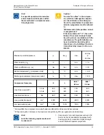
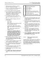
p
p
0
Δp
π
t
0h
t
e
t
c
t
oil
Maximum permitted pressure
Suction pressure
Pressure difference
Pressure ratio
Suction temperature (compressor inlet)
Discharge temperature (compressor outlet)
Condensing temperature
oil inlet temperature into the compressor
Notes:
1. During tests of a certain application case, all the
conditions specified in the table must be consid-
ered and adhered to.
2. Should the given limits not be adhered to in indi-
vidual cases, then the manufacturer needs to be
contacted.
3. In addition to the application limits stated in the
tables, the applicable operating conditions of the
compressor type in question must also be con-
sidered (e. g. start-up regime, oil pressure, oil
quantity etc.).
4. Depending on the refrigeration requirements,
economiser operation takes place at a control
slide position between 100% and approx. 70%
control slide position.
5. When using
R134a
as a refrigerant and a
evap-
orating temperature > 60 °C
consultation with
the manufacturer must be made.
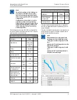
7.12.5
Water quality requirements,
parameters
All water bearing components from the manufacturer
deliver an optimum performance and provide maxi-
mum protection from corrosion, provided you meet
all of the limiting values recommended in VDI 3803
issue 2010-02 (Tab. B3) for non-corrosive water and
adequate water conditioning.
Description of Design and Function
Operating Manual | GEA Grasso M-Series
Screw Compressor Packages
50
GEA Refrigeration Germany GmbH | P_261511_1 | Generated 01.04.2015
Содержание Grasso M-Series
Страница 88: ......

