background image

09

430

-08

.2

01

6-

Gb

17

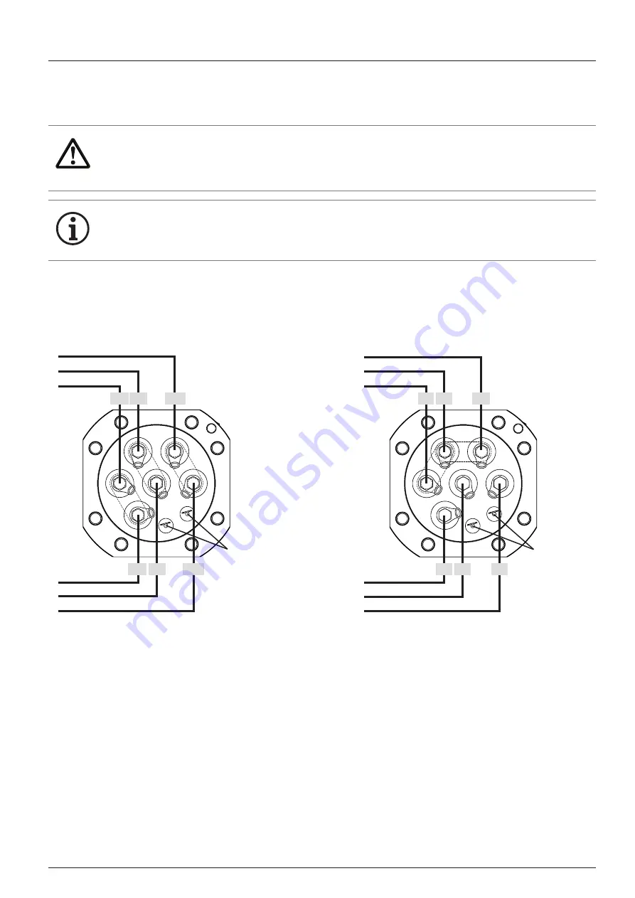
4.3  Connecting the electrical connections on the terminal board

Terminal assignment on the terminal board
Standard part winding

Terminal assignment on the terminal board
Star delta

WARNING


X

Make sure that you use the correct connection on the cable harnesses!


NOTE

The drawings show the underside of the terminal board.

3
2
1

Connections for
PTC sensors

1U11V1

1W1

7
8
9

2U1 2V1

2W1

blue

black

red

U1 V1

W1

blue

red

black

W2 U2

V2

Part winding 1

Part winding 2

Cable loom 1

Cable loom 2

Connections for
PTC sensors

Assembly

Содержание Bock HGX2 CO2 T Series

Страница 1: ...Repair instruction electric motor Series HGX2 CO2 T HGX34 CO2 T HGX46 CO2 T HGX34 CO2 T HGX2 CO2 T 09430 08 2016 Gb Translation of the original instructions ...

Страница 2: ...ctrical work may only be carried our by a qualified electrician Alternatively on a country specific basis persons who have undergone electrotechnical instruction and who have proof of their qualification are also permitted to carry out the work DANGER This symbol refers to instructions for avoiding direct severe dangers to persons or plant by electrical current DANGER This symbol refers to instruc...

Страница 3: ...X Before you carry out any repair work disconnect the compressor from the electricity network X X Turn the main switch to O OFF X X Secure the main switch against an unauthorised restart WARNING The heavy weight of the compressor can be potentially dangerous Use all the seals included in the kit ...

Страница 4: ... work 3 1 Draining the oil NOTE Do not dispose of oil in domestic waste X X Dispose of the old oil in accordance with the environmental regulations and observe national regulations Remove the screw plug M22 AF19 and the seal ring HGX34 CO2 T HGX46 CO2 T HGX2 CO2 T Remove the screw plug M26 AF24 and the seal ring ...

Страница 5: ...t the terminal box the oil sump heater can remain in the compressor housing Remove the terminal box cover 4 hexagon head screws if available Loosen the electrical connections on the terminal board and on the motor protection device Remove the terminal box 4 hexagon head screws M6 AF10 Remove the terminal board 8 cylinder head screws M10 AF8 Remove the electrical lines from the underside of the ter...

Страница 6: ...rous risk of falling danger of crushing X X ATTENTION The residual oil flows out when the motor cover is removed X X Lay an absorbent material under the area and dispose of it in accordance with the environmental regulations HGX2 CO2 T Loosen the hexagon head screws M12 AF19 Remove the motor cover with the seal ring Disassembly ...

Страница 7: ...ed off the compressor housing For this purpose screw two suitable screws M10 evenly into both threads on the opposite side in order to squeeze off the motor cover The flat gasket is destroyed in the process Take off the motor cover with the seal and the O ring X X Carefully clean the sealing surface from old flat gasket material Disassembly ...

Страница 8: ...rewing two round rods of the correct height in two holes opposite one another of the motor housing Prevent inadvertent rolling of the removed stator Carefully pull the stator out of the compressor housing and pay attention to the cable Loosen the threaded pin of the stator protection M8 AF4 The threaded pin is glued in For easier disassembly warm up the threaded pin with an hot air blower X X Prot...

Страница 9: ...09430 08 2016 Gb 9 3 5 Disassemble the rotor Disassembly Loosen the rotor srew M12 AF19 Pull off rotor from crankshaft In case of stiffness use take off device ...

Страница 10: ...otor housing Align the stator so that the cable harness is positioned upwards and the feather key is aligned with the groove of the stator X X Do not damage any cables and components WARNING The heavy weight of the stator can potentially be dangerous risk of falling danger of crushing X X Use a suitable hoist for the removal X X Note the direction of the feather key stator You must align the parts...

Страница 11: ...tors without dimension X are inserted up to the stop into the compressor housing For the threaded pin for securing the stator a countersink has to be provided X X For this purpose use a drill with Ø 6 8 mm and a drill tip of 90 Bore a hole into the stator by observing the dimension Y but only use a drill with cone tip X X Carefully remove the chips e g with a vacuum cleaner max 75kg Y Dimension Y ...

Страница 12: ...stance CH stator for the 15 kW motor 30 8 1 5 CH compressor housing HGX34 CO2 T HGX2 CO2 T X X Description X in mm Distance CH stator for the 9 kW motor 60 1 5 Distance CH stator for the 11 kW motor 45 1 5 Distance CH stator for the 15 kW motor 65 1 5 Distance CH stator for the 18 5 kW motor 49 1 5 CH compressor housing Assembly ...

Страница 13: ...r this purpose use a drill with Ø 6 8 mm and a drill tip of 90 Bore a hole into the stator by observing the dimension Y 62 4 0 5 mm but only use a drill with cone tip X X Carefully remove the chips e g with a vacuum cleaner WARNING The heavy weight of the stator can potentially be dangerous risk of falling danger of crushing X X Use a suitable hoist for the removal X X Note the direction of the fe...

Страница 14: ...p until the dimension X see table page 12 Motors without dimension X are inserted up to the stop into the compressor housing X X At the same time carefully pull the cables upwards through the terminal board opening Align the stator so that the countersink for the threaded pin in the stator is aligned with the countersink of the female thread in the compressor housing Assembly instructions for HGX2...

Страница 15: ...Degrease the threaded hole for the threaded pin e g with brake cleaner spray X X Screw in the new threaded pins INFO X X The hardening time of the thread coating is 6 hours The threaded pin is coated and may only be used once X X Observe the tightening torques Assembly ...

Страница 16: ...sembling the terminal board Connect the electrical connections as per the illustration on page 17 Install the terminal board and the seal with 8 cylinder head screws M10x30 60 Nm INFO X X Observe the tightening torques Assembly ...

Страница 17: ...the terminal board Star delta WARNING X X Make sure that you use the correct connection on the cable harnesses NOTE The drawings show the underside of the terminal board 3 2 1 Connections for PTC sensors 1U11V1 1W1 7 8 9 2U1 2V1 2W1 blue black red U1 V1 W1 blue red black W2 U2 V2 Part winding 1 Part winding 2 Cable loom 1 Cable loom 2 Connections for PTC sensors Assembly ...

Страница 18: ...rankshaft X X Screw in the new screw M12x70 with the disk 65 Nm INFO X X Note the direction of the feather key rotor You must align the parts in order to install them X X The screw is adhesive coated and must only be used once X X Observe the tightening torques Assembly ...

Страница 19: ... O ring and place it into the groove on the motor cover Install the motor cover and the new flat gasket with 24 cylinder head screws M12x40 HGX2 CO2 T X X Slightly oil the new O ring Install the motor cover and the O ring with 24 hexagon head screws M12x45 130 Nm 130 Nm INFO X X Observe the tightening torques Assembly ...

Страница 20: ... and the motor protection device X X Install the terminal box cover Make sure that the sealing lip is not damaged Connect the oil sump heater on the terminal box 8 5 Nm 15 Nm INFO X X Mount all cable screws to the terminal box with care so the the IP protection type continues to be guaranteed X X Observe the tightening torques Assembly ...

Страница 21: ...w plug and the seal ring DANGER X X Carry out the additional work steps such as filling the oil et c as per the assembly instruction See the assembly instruction in particular the Start up chapter 100 Nm INFO X X Observe the tightening torques Assembly ...

Страница 22: ...about installation operation and accessories please contact our technical service or your refrigerating system wholesaler or our representative Any suggestions you may have regarding the on going development of our compressor equipment and spare parts range are welcome at any time Yours faithfully GEA Bock GmbH Benzstraße 7 72636 Frickenhausen Germany ...

Страница 23: ...09430 08 2016 Gb 23 ...

Страница 24: ...r values Excellence Passion Integrity Responsibility GEA versity GEA Group is a global engineering company with multi billion euro sales and operations in more than 50 countries Founded in 1881 the company is one of the largest providers of innovative equipment and process technology GEA Group is listed in the STOXX Europe 600 index ...

Отзывы: