40
D
GB
F
E
I
96403-08.2019-DGbFEIRu
8
|
Accessories
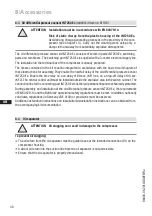
8.3 Oil differential pressure sensor INT250 Ex
(retrofit kit item no. 81196)
The oil differential pressure sensor kit INT250 Ex consists of screw-in parts INT250 Ex, switching
parts and two timers. The switching part INT250 Ex is supplied with a 3-meter electrical supply line.
The installation in the terminal box of the compressor is already prepared.
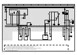
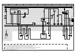
The timers contained in the kit must be integrated in accordance with the basic circuit diagram of
these instructions for assembly, They enable the rise/fall delay of the oil differential pressure sensor
INT250 Ex. Enable the time relay on a on delay of 90 sec. (KF1) res. on a drop-off delay of 90 sec.
(KF2). The central control unit must be installed outside the explosive area in the switch cabinet. The
connection line for the connecting part INT250 Ex must be laid permanently and mechanically protected.
During assembly and installation of the oil differential pressure sensor INT250 Ex, the requirements
of EN 60079-14 and the BetrSichV operational safety regulations must be met. In addition, nationally
valid laws, regulations (in Germany VDE 0100) or provisions must be observed.
Additional installation instructions and installation/deinstallation instructions can be obtained from
the accompanying kit documentation.
To prevent oil slugging:
The oil return from the oil separator must be guided back at the intended connection (D1) on the
compressor housing.
A direct oil return into the suction line from the oil separator is not permissible.
Ensure that the oil separator is properly dimensioned.
8.4 Oil separator
ATTENTION Oil slugging can result in damage to the compressor.
ATTENTION Installation must be in accordance with EN 60079-14.
Risk of static charge from the plastic housing of the INT250 Ex.
Avoid strong charge-generating processes in the proximity of the com
-
pressor (see Chapter 1.3). Carry out the cleaning work using only a
damp cloth and away from potentially-explosive atmospheres.

