


24
D
GB
F
E
I
96403-08.2019-DGbFEIRu
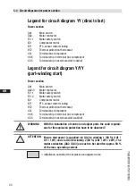
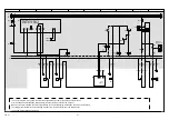
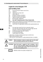
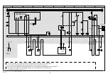
Legend for circuit diagram Y/YY
(part-winding start)
Power section
QA1
Main switch
QA2/3
Motor contactor
FC1.1
Motor safety switch
FC1.2
Motor safety switch
EC1
Compressor motor
BT1
PTC-sensor motor winding
BT2
Thermal protection thermostat
UC1
Terminal box compressor
X KK
Terminal strip in terminal box compressor
X SS
Terminal strip in external switch cabinet
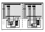
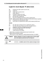
Legend for circuit diagram YY (direct start)
= Installation outside of the explosion endangered area
Power section
QA1
Main switch
QA2
Motor contactor
FC1.1
Motor safety switch
EC1
Compressor motor
BT1
PTC-sensor motor winding
BT2
Thermal protection thermostat
UC1
Terminal box compressor
X KK
Terminal strip in terminal box compressor
X SS
Terminal strip in external switch cabinet
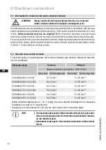
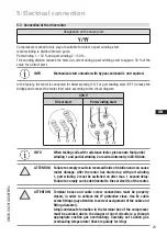
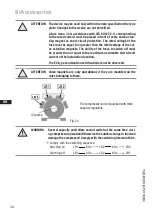
5.4 Circuit diagrams for power section
ATTENTION Ensure that power is supplied via QA2 to winding 1 (50 %) (1U1 /
1V1 / 1W1) and via QA3 to winding 2 (50 %) (2U1 / 2V1 / 2W1). The
motor contactors (QA2 / QA3) are each to be rated for approx. 50 %
of the max. operating current.
WARNING
With the installation of control and adjust parts the valid regulati-
ons for the explosion protection have to be observed!


