22
D
GB
F
E
I
96403-08.2019-DGbFEIRu
5
|
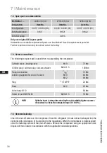
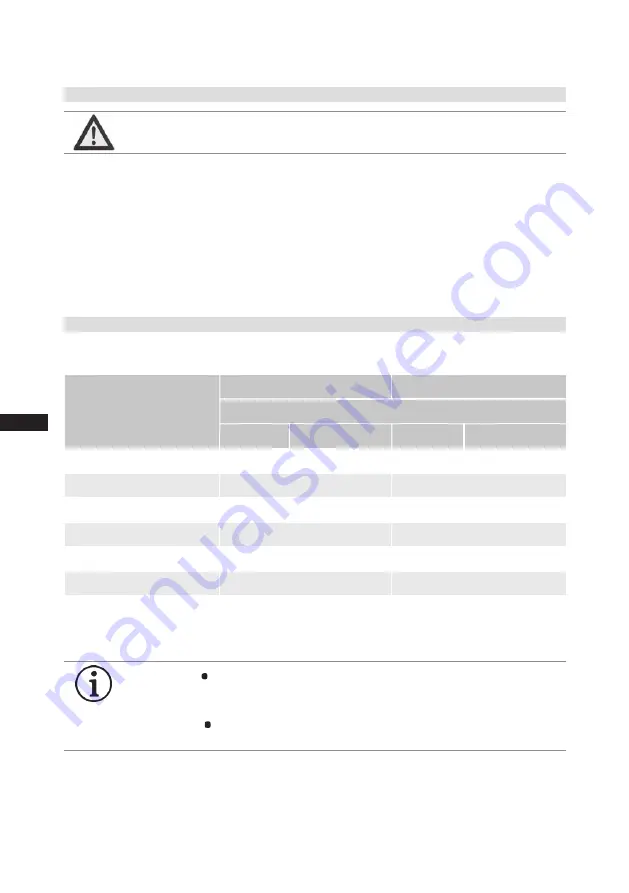
Electrical connection
Compressor type
Onshore
Offshore
Minimum terminal cross section 400V / 50 Hz
Direct start Part winding start
Direct start
Part winding start
EX-HG88e/2400-4 3G (HC)
6 x 35 mm²
6 x 35 mm² *
)
EX-HG88e/2400-4 S 3G (HC)
6 x 35 mm²
6 x 35 mm² *
)
EX-HG88e/2735-4 3G (HC)
6 x 35 mm²
6 x 35 mm² *
)
EX-HG88e/2735-4 S 3G (HC)
6 x 35 mm²
6 x 35 mm² *
)
EX-HG88e/3235-4 3G (HC)
6 x 35 mm²
6 x 35 mm² *
)
EX-HG88e/3235-4 S 3G (HC)
6 x 35 mm²
6 x 35 mm² *
)
- Where ambient temperatures are > 35 °C, supply lines and cable/line bushings with a temperature
resistance of at least 95 °C must be used.
*
)
If supply line cross-sections of 6 x 50 mm
2
are used, these can be of standard grade.
5.1 Information for contactor and motor contactor selection
5.2 Terminal cross section for leads
To limit the heating of conducting parts, the minimum terminal cross sections, indicated in the table
have to be followed.
INFO
The insulation plate used on the terminal board serves to guarantee
the air and creepage paths. It is therefore essential that it remains
on the terminal board.
Use tubular cable lugs for the electrical connection to the terminal
board.
All protection devices and switching or monitoring units must be fitted in accordance with the local
safety regulations and established specifications (e.g. VDE) as well as with the manufacturer’s infor
-
mation.
Motor protection switches are required!
Motor contactors, feed lines, fuses and motor
protection switches must be rated on the basis of the maximum working current (see name plate).
For motor protection use a current-dependent and time-delayed overload protection device for moni
-
toring all three phases. Set the overload protection device so that it must be actuated within 2 hours,
if there is 1.2 times the max. working current.
WARNING
Always install all electrical peripheral devices in an external
control cabinet outside the explosion-endangered area!


