GE UVD-EVRDNR(-P) Скачать руководство пользователя страница 7


Components 

The UVD-EVRDNR cameras consist of the following parts: 
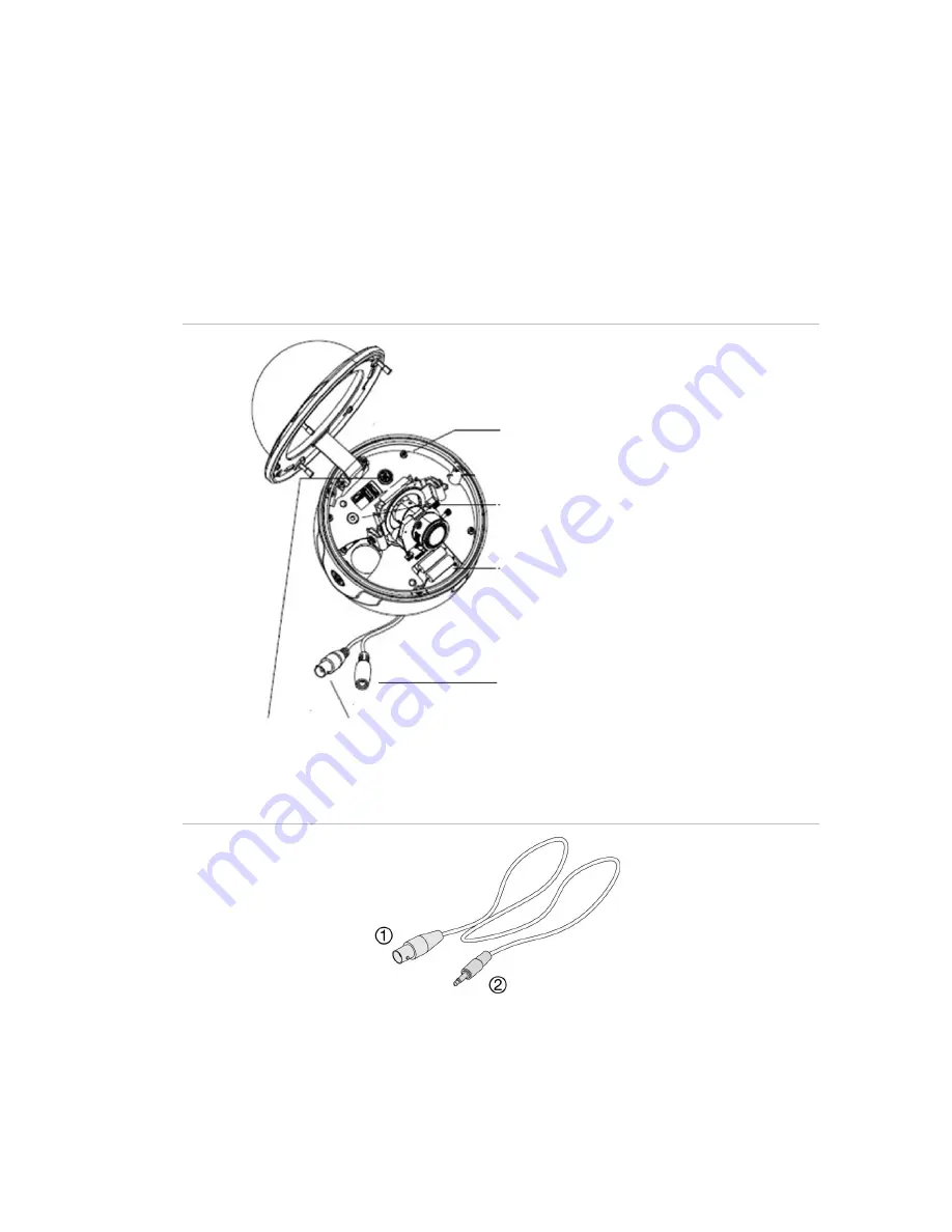
•  The camera assembly (Figure 1 below) 
•  Monitor output cable (Figure 2 below) 
•  Mounting screws, wall anchors, and hex key 
Use the video output BNC and power jack for normal system operation. Use the 
monitor output cable for installation and maintenance. 

Figure 1: Camera assembly 


Camera body 


Video monitor output 


System heater 


Power jack 

OSD control pad  

Video output BNC 


Figure 2: Monitor output cable 


1. Monitor output BNC 

2. Monitor output RCA 


UVD-EVRDNR(-P) Camera User Manual 

Содержание UVD-EVRDNR(-P)

Страница 1: ...GE Security REV 01 00 ISS 02SEP09 UVD EVRDNR P Camera User Manual...

Страница 2: ...or visit us online at www gesecurity com FCC compliance This equipment has been tested and found to comply with the limits for a Class A digital device pursuant to part 15 of the FCC Rules These limi...

Страница 3: ...ion 7 Angle adjustment 7 Focus adjustment 8 Connect the monitor 8 Programming 8 Setup menu 8 Camera identification 9 Light control 10 Manual exposure menu 11 Day Night control 12 White balance 14 Pict...

Страница 4: ......

Страница 5: ...ctrical wiring and low voltage electrical connections Read these instructions and all ancillary documentation entirely before installing or operating this product Note A qualified service person compl...

Страница 6: ...ife and high reliability OSD control allows eight masks to be shown on the screen for subjects requiring special protection due to privacy concerns Advanced OSD onscreen display control Signal to nois...

Страница 7: ...and hex key Use the video output BNC and power jack for normal system operation Use the monitor output cable for installation and maintenance Figure 1 Camera assembly Camera body Video monitor output...

Страница 8: ...he right to select or adjust the parameters of the selected item Down Moves the cursor downward to select an item Enter Press the center of the control pad to display the Setup menu If the selected it...

Страница 9: ...may be used for ground Camera installation To mount the camera attach the camera to the mounting surface using the appropriate fasteners Angle adjustment To adjust the horizontal angle of the platform...

Страница 10: ...d video monitor to the system To connect the monitor do the following 1 Plug the monitor output cable Figure 2 on page 5 to the video monitor output connector Figure 1 on page 5 2 Connect the BNC cabl...

Страница 11: ...or to Unlock and press Enter To unlock the Setup menu press Up Down and then press Enter in that order Camera identification To set the camera ID do the following 1 Move the cursor on the Setup menu F...

Страница 12: ...ra ID display 8 Press Up Down Right or Left to move the Camera ID to the desired position 9 Press Enter to fix the ID position and return to the previous menu Light control To adjust the light control...

Страница 13: ...or Right to adjust the Av Pk value on the DC iris lens after level setting Av value The electronic convergence is automatically adjusted for the average photometric method with the average video sign...

Страница 14: ...eturn and press Enter to set the manual exposure and return to the previous menu Day Night control To adjust the white balance do the following 1 Move the cursor on the Setup menu Figure 6 on page 9 t...

Страница 15: ...15 below 7 Move the cursor on the Schedule menu to the D N time position Press Left or Right to set hour from 0 23 and minute from 0 to 59 8 Move the cursor on the Schedule menu to the N D time positi...

Страница 16: ...adjusts the WB itself To adjust the white balance do the following 1 Move the cursor on the Setup menu Figure 6 on page 9 to White Bal 2 Press Left or Right to cycle between ATW AWB and PTL 3 To set...

Страница 17: ...silhouetted Press Left or Right to select BLC on or BLC off 6 Move the cursor to the AGC automatic gain control position Increasing the AGC level increases camera sensitive at lower light levels Press...

Страница 18: ...elected press Enter to display the Ext Sync menu 4 Press Left or Right to align the sync phase Mirror To adjust the mirror do the following 1 Move the cursor to the Mirror position 2 Press Left or Rig...

Страница 19: ...ange the mask position and press Enter when the desired position is selected 6 Move the cursor to Size and press Enter Press the Up Down Left or Right to change the mask size and press Enter when the...

Страница 20: ...Menu Map...

Отзывы: