


Critical Power
Modifications reserved
Page 129/146
GE_UPS_OPM_TLE_SCE_M60_M80_1GB_V020.docx
User Manual
TLE Series 600 & 800 CE S1
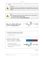
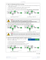
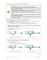
NOTE !
Ensure the
LED 1 (Rectifier)
is lit before carrying out this procedure.
It indicates that the DC-Link has reached 800Vdc (see screen
MEASURES / Rectifier)
!
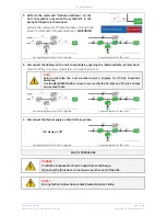
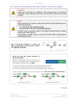
3. Connect the Battery on the Unit to reconnect by closing the
“External Battery Protections”.
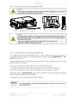
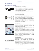
Synoptic diagram of the unit to reconnect
Synoptic diagram of other units
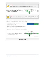
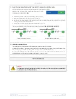
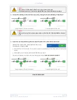
NOTE !
Before performing the next procedure make sure that the LED 3
(Booster/Battery charger)
is lit.
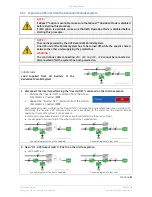
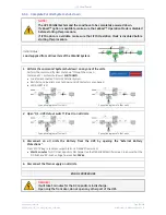
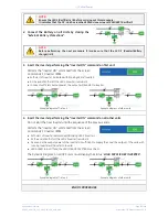
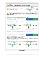
4.
Insert the inverter performing the command "Inverter ON”
on the Unit to reconnect
.
Perform the
“Inverter ON”
command from the screen:
Commands 1 / Inverter /
ON
.
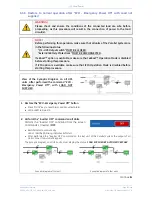
After
Soft-start
of the
Inverter
, the
Inverter
connects automatically to the
other Units
of the
Parallel
System
.
LED ALARM
turns Off and the
LED LOAD PROTECTED
must be lit.
The
Synoptic Diagram
, on all UPS units, must display the status
“
LOAD SUPPLIED BY INVERTER
”
.
Synoptic diagram of the unit to reconnect
Synoptic diagram of other units
END OF PROCEDURE


