


Modifications reserved
Page 55/79
OPM_SGS_USM_M22_M30_2US_V010.doc
User Manual
SG Series 225 & 300 UL S2
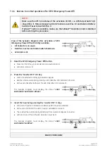
7.1.6 Restore to normal operation after EPO (Emergency Power Off)
NOTE !
Make sure the UPS to be status of the activation of
EPO
, i. e.
UPS Output Switch Q1
closed (Pos. I),
Manual Bypass Switch Q2 (option)
open (Pos. O) and
External Battery
Switch or Fuses
connected (Pos. I).
If
eBoost™
option is available, make sure that
eBoost™ Operation mode
is disabled
before starting this procedure.
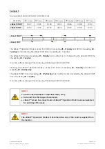
View of the
Synoptic Diagram
after activation of
EPO
(Emergency Power Off)
with
Utility
available.
•
All
Contactors
are open.
•
Rectifier
,
Inverter
and
Static-Switch
shutdown.
•
LED Alarm
is lit.
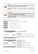
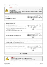
1. Reset the EPO (Emergency Power Off) button
.
•
Press the
“MUTE”
key to reset
alarm
and a
coustical alarm
.
•
LED Alarm
remains lit.
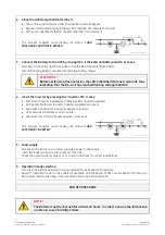
2. Press the “Inverter OFF” ( O ) key
.
•
Load
is transferred to
Utility
by
Automatic Bypass
.
•
Rectifier
starts automatically, blinking
LED 3 (Rectifier ON)
indicates Soft-start.
•
At the end of
Rectifier
Soft-start the
LED 3 (Rectifier ON)
remains lit.
The
Synoptic Diagram
must display the status
“
LOAD
SUPPLIED BY AUTOMATIC BYPASS
”
.
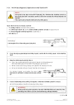
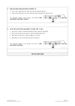
3. Insert the Inverter by pressing the
“
Inverter ON” ( I ) key
.
•
Soft-start of
Inverter
indicated with blinking
LED 5 (Inverter available)
.
•
At the end of Soft-start the
LED 5 (Inverter available)
remains lit.
•
The
Load
will be automatically transferred from
Automatic Bypass
to
Inverter
.
•
LED Alarm
turn Off and the
LED Operation
must be lit.
The
Synoptic Diagram
must display the status
“
LOAD
SUPPLIED BY INVERTER
”
.
END OF PROCEDURE


