


Modifications reserved
Page 63/79
OPM_SGS_USM_M22_M30_2US_V010.doc
User Manual
SG Series 225 & 300 UL S2
7.2.3 From Manual Bypass Q2 (option) to normal function VFI
NOTE !
UPS Parallel System
has been turned
OFF
following the
“Maintenance shutdown
(Load on Manual Bypass Q2)”
procedure and the
Load
is still powered by all
Manual
Bypass Q2 (option)
.
The
Load
must be transferred back to the
UPS Parallel System
.
Open the front door on all UPS units and make sure that:
•
The
safety screens
are fixed in their position.
•
The
UPS Output Switches Q1
and the
External Battery Switch or Fuses
are open (Pos. O).
•
The
Manual Bypass Switches Q2 (option)
are closed (Pos. I).
•
LED Alarm
are lit.
Initial status:
Load supplied from all Manual Bypass Q2 of the Parallel
System
.
All Manual Bypass Switches Q2 of the Parallel System
are closed.
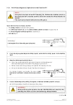
1. If not already supplied (separate utility inputs), switch-ON the utility power to the rectifier
input on all UPS units.
2. Close the UPS output switch Q1 (Pos. I) on first Unit
.
•
Rectifier
starts automatically, blinking
LED 3 (Rectifier ON)
indicates Soft-start.
•
At the end of
Rectifier
Soft-start,
LED 3 (Rectifier ON)
remains lit.
Synoptic diagram of first unit
Synoptic diagram of other units
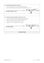
3. Connect the Battery on first Unit by closing (Pos. I) its External Battery Switch or Fuses.
LED 4b
(Charging Battery)
should be lit indicating
battery charge
.
ATTENTION !
Before performing this operation, the
LED 3 (Rectifier ON)
must remain lit, thus
indicating that the DC-Link has reached floating voltage (540Vdc)!
Continue
►


