


Modifications reserved
Page 46/79
OPM_SGS_USM_M22_M30_2US_V010.doc
User Manual
SG Series 225 & 300 UL S2
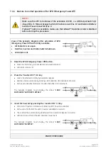
NOTE !
During the first commissioning
SG Series 225 & 300
requests a set up of the UPS
configuration parameters presented in the following screens.
Without such configuration it is not possible to continue with the commissioning
procedure.
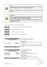
WARNING !
The setup of the UPS configuration parameters must be done only
by a GE GLOBAL SERVICES FIELD ENGINEER.
The setup of mistaken values could compromise the integrity and
reliability of the UPS.
In this mode the keys perform the following functions:
Confirm the selection made and select the next parameter.
ESC
Re-establish default value.
Modify or insert the selected value.
Save the configuration of set parameters.
`
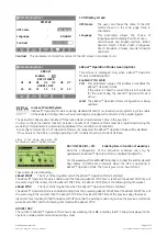
Configuration
DISPLAY CONFIGURATION
Select language
:
ENGLISH
ESC
DISPLAY CONFIGURATION screen
Select language
This parameter allows the choice of language used to display
the information.
Pushing the pushbuttons
“1
st
button” (METER)
and
“2
nd
button”
(ALARM)
together automatically sets the
LCD
communication for
“ENGLISH”.
`
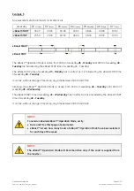
Configuration
UPS CONFIGURATION
Input frequency
:
60
Hz
Output frequency
:
60 Hz
Inverter voltage
:
277
V
ESC
UPS CONFIGURATION screen
Input frequency
Rectifier input frequency value.
The default value is 60Hz and shall not be changed.
Output frequency
Inverter output frequency value.
The default value is 60Hz and shall not be changed.
Inverter voltage
Output voltage PHASE/NEUTRAL of the inverter (default 277V).
Continue
►


