– 54 –
Note:
Care must be taken to prevent the spring from
falling into the burner box.
Use a small needle-nose pliers and remove the
4.
clip and spring from the igniter.
Clip
Spring
Pull out the igniter from the burner base.
5.
Note:
When installing, replace the inner two T-20
Torx center screws
fi
rst. Partially tighten the T-15
Torx screw opposite the igniter and align the
remaining screw holes. Replace the remaining 2
screws.
Surface Burner Igniters
This range uses two different igniters. The igniters
for the 3 single burners are inserted through the
main top and attached to the burner brackets. The
dual burner uses an igniter that is attached to the
burner head. The following describes the procedure
to remove the dual burner igniter.
To remove the dual burner igniter:
Remove the burner cap and head.
1.
Using a T-15 Torx driver, back out the Torx screw
2.
opposite the igniter 9 turns.
Do not remove.
Remove the outer two T-15 and the inner two
3.
T-20 Torx screws, then lift the dual burner base to
access the igniter.
(
Continued next page
)
Содержание Profile PGS968
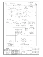
Страница 74: ... 74 Continued next page PGS908 Schematic ...
Страница 76: ... 76 Continued next page PGS968 Schematic ...
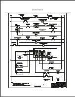
Страница 77: ... 77 THERMAL SWITCH THERMAL LINE BREAK PGS975 Wiring Diagram Continued next page ...
Страница 78: ... 78 PGS975 Schematic ...


