background image

– 5 –

  Water Valve Assembly ........................................................................................................................................................ 45

  Inverter Compressor............................................................................................................................................................ 46

  Inverter ...................................................................................................................................................................................... 46

  Main Board ............................................................................................................................................................................... 47

  Main Board Connector Locations .................................................................................................................................. 48

Diagnostic Mode ..............................................................................................................................................................................50

Schematic Diagram .......................................................................................................................................................................51

Monogram Refrigerator Warranty ..........................................................................................................................................52

Index ......................................................................................................................................................................................................53

Содержание Monogram ZIPS360NHSS

Страница 1: ...ZIPS360NHSS ZIPP360NHSS ZIP360NH GE Monogram 36 Built In French Door Refrigerator Technical Service Guide August 2016 GE Appliances 31 9259 GE Appliances Louisville Kentucky 40225...

Страница 2: ...th its use WARNING To avoid personal injury disconnect power before servicing this product If electrical power is required for diagnosis or test purposes disconnect the power immediately after perform...

Страница 3: ...from F to C Installation 10 Door Alarm 10 Sabbath Mode 10 Installation 11 Water Line 11 Anti Tip Device 12 Secure Refrigerator to Cabinetry 12 Level Refrigerator 13 Connect Water Supply 13 Fresh Food...

Страница 4: ...ost Cooling Operation 32 Adaptive Defrost Pre Chill Operation 32 Defrost Heater Operation 32 Dwell Period 32 Cabinet Bottom 33 Cabinet Bottom Component Locator 33 Toe Kick Installation 33 LU RZ DQG DQ...

Страница 5: ...5 Water Valve Assembly 45 Inverter Compressor 46 Inverter 46 Main Board 47 Main Board Connector Locations 48 Diagnostic Mode 50 Schematic Diagram 51 Monogram Refrigerator Warranty 52 Index 53...

Страница 6: ...shoes for all repairs Steel Toed Work Boot Electrically Rated Glove and Dyneema Cut Resistant Glove Keeper Dyneema Cut Resistant Glove Plano Type Safety Glasses Prescription Safety Glasses Safety Glas...

Страница 7: ...2016 G 2015 F 2014 D 2013 A Brand Z Monogram Z I P P 3 6 0 N H A S S Configuration P French Door Bottom Freezer Engineering Digit 0 99 Model Year 2014 Handle Options SS Stainless case handle Door Pan...

Страница 8: ...XVH RI ZDWHU OWUDWLRQ WKH icemaker produces OWHUHG LFH FXEHV 7ZR EDVNHWV SURYLGH DPSOH VWRUDJH IRU IUR HQ JRRGV 7KH WRS EDVNHW LV LQGHSHQGHQW IURP the lower basket and is able to fully extend Cooling...

Страница 9: ...Chg 9 25 oz Electrical Shock Hazard Death or serious injury can result from failure to follow these instructions 6HUYLFH E D TXDOL HG VHUYLFH WHFKQLFLDQ RQO Disconnect power before servicing this prod...

Страница 10: ...hours for the refrigerator to reach the temperature that has been set NOTE Setting the controls to OFF stops cooling but GRHV QRW VKXW R HOHFWULFDO SRZHU WR WKH UHIULJHUDWRU 34 F 1 C 6 F 21 C 41 F 5...

Страница 11: ...e long enough to extend to the front of the refrigerator Allow enough tubing to accommodate the bend leading into the water line connection NOTE The only GE approved plastic tubing is supplied in the...

Страница 12: ...l out on the end of the rod to make sure it is secure in the bracket 5 Locate the hole on the rod that is closest to the unit A hair pin cotter will be put through this hole to secure the rod If this...

Страница 13: ...pening to shorten the opening Any attempt to raise the refrigerator more than 1 inch will damage the front leveling legs and the rear leveling wheels CAUTION Level Refrigerator Hex Nut Adjusts Rear Wh...

Страница 14: ...addition of heavy door panels may have caused the doors to move slightly out of alignment Check to be sure the top of the doors are evenly aligned with each other If necessary the doors may be adjuste...

Страница 15: ...2 Using clamp plyers remove the closure spring from the actuator arm 3 Using a 3 16 in Allen wrench remove the bolt mounting the actuator arm to the door 4 Remove the actuator arm 5 Remove four T25 To...

Страница 16: ...to ensure the main board is supplying voltage to the circuit The vertical mullion is located on the left fresh food door The mullion contains a heater which is supplied with 13 VDC from the main board...

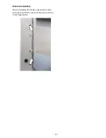
Страница 17: ...17 Mullion Reinstallation When reinstalling the mullion ensure the mullion spring is seated in the recess of the door as shown in the image below...

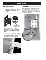
Страница 18: ...ot remove the eight 3 Phillips screws four per bracket holding the L brackets to the front drawer panel 3 The holes in the L bracket are key hole shaped Pick up on the drawer front to allow the screw...

Страница 19: ...t to obtain proper sealing of the drawer gasket to the cabinet frame It is not necessary to remove the slides to remove the evaporator cover The upper freezer drawer slide assemblies are mounted just...

Страница 20: ...door switches 2 Top mullion striker 3 Inlet air passages 4 HMI assembly 5 Vegetable pan slides 6 Deli pan slides 7 Return air passage 8 Lower LED lighting 9 Upper LED lighting 10 Fresh food thermistor...

Страница 21: ...V WKDW W IRRG VWRUDJH QHHGV To remove shelves Tilt shelf up at front then lift it up and out of the tracks on rear wall of refrigerator To replace shelves Select desired shelf height With the shelf fr...

Страница 22: ...of nuts and bolts join the slides to the brackets Each slide will rest on two locating pins which aid installation of the new parts Fresh Food Lighting The LED lighting in the fresh food compartment...

Страница 23: ...e pulled from the cabinet Upper and lower LED boards are mounted with two plastic retainer pins LED boards can be removed by squeezing in on the sides of the pins then pulling down on the board and di...

Страница 24: ...lsius and Fahrenheit reset the ZDWHU OWHU DQG VHW WKH GRRU DODUP HMI Removal 1 Remove the light shield 2 Remove the light housing see the Damper Damper Removal section in this service guide 3 Score th...

Страница 25: ...reezer drawer slides 4 Upper basket slides 5 Icemaker diverter 6 Icemaker 7 FHPDNHU OO WXEH 8 Icemaker electrical connector 9 Evaporator cover 10 Freezer LED lighting 11 Freezer fan cover 12 Freezer t...

Страница 26: ...n the freezer drawer 2 Lift up the back of the basket then slide the basket back until it clears the front hooks Ensure that the freezer drawer is fully closed after each opening to maintain normal op...

Страница 27: ...aker After the icemaker has been turned on again there will be a delay of about 45 minutes before the icemaker resumes operations The ice bucket is conveniently located in the upper freezer basket Occ...

Страница 28: ...g defrost the water valve relay will not be energized The water valve will require input from the icemaker to energize the K3 relay 7KH LFHPDNHU UHOD ZLOO WXUQ RQ 0 2 WLPH DIWHU WU LQJ WR OO WR PLQXWH...

Страница 29: ...s screws Evaporator Cover The freezer evaporator cover is located at the rear of the freezer compartment It is removable with the icemaker removed and all of the drawer slides left in place 1 Remove t...

Страница 30: ...ner clips 3 Defrost heater 4 Evaporator thermistor 5 140 F safety TCO 6 Freezer fan assembly 7 Fresh food fan assembly 2 3 6 7 4 5 1 2 Evaporator Component Locator See the LU RZ DQG DQV section for mo...

Страница 31: ...will be spliced in its place NOTE It is important to follow proper procedure for splicing wires New connections should use bell FRQQHFWRUV OOHG ZLWK D VLOLFRQH JUHDVH VXFK DV WR97X163 or equivalent D...

Страница 32: ...rature using evaporator thermistor inputs Typically the evaporator thermistor will sense a temperature of 45 F within approximately 16 minutes When the thermistor senses 45 F the main control board wi...

Страница 33: ...sembly with the three screws provided and adjust to the desired height and tighten the screws A custom toe kick can be installed to match or complement the surrounding cabinetry Use the supplied toe k...

Страница 34: ...icemaker and to the right The air then circulates down and is pulled back though the bottom of the evaporator cover The fresh food fan utilizes a 12 VDC motor to circulate freezer air into the fresh f...

Страница 35: ...n speed and varies the length and frequency of the 13 6 VDC pulse The main control board monitors the speed of the motor and adjusts the PWM Freezer Fan Removal 1 Remove the freezer drawer front 2 Rem...

Страница 36: ...far to the right as possible NOTE When moving the compressor take care not to kink or break refrigerant lines Condenser Fan The freezer fan uses four wire connections White Wire DC Common The white w...

Страница 37: ...5 pink J2 pin 3 white 4 12 VDC Freezer Fan Resistor Condenser Fan Resistor Condenser Fan Resistor Freezer Fan Resistor Drain Pan Fan The drain pan fan utilizes a 12 VDC motor to FLUFXODWH DLU XQGHU WK...

Страница 38: ...Duty 12 13 VDC FZ Fan Low 2143 RPM FZ Fan Med 2400 RPM FZ Fan High 6000 RPM max FF Fan Low 29 00 Duty Cycle 3 5 4 5 VDC FF Fan Med 35 00 Duty Cycle 4 5 5 VDC FF Fan High 41 50 Duty cycle 5 5 6 VDC Dra...

Страница 39: ...However the compressor does not run enough to bring the freezer down to 0 F At lower room temperatures the ambient thermistor alters the main control board s calculations for the target temperature T...

Страница 40: ...TE It is important to follow proper procedure for splicing wires New connections should use bell FRQQHFWRUV OOHG ZLWK D VLOLFRQH JUHDVH VXFK DV Part WR97X163 or equivalent Fresh Food Thermistors The f...

Страница 41: ...the main board approximate operating voltages can be read at the J1 J5 and J14 connectors J1 pin 5 brown J14 pin 4 white 5 VDC Any voltage higher than 4 VDC or lower than 1 VDC indicates a failed humi...

Страница 42: ...oop Process Tube Suction Line Muffler Auxiliary Condenser Hot Wall Condenser Foamed in place Process Tube Suction Line 0X HU Condenser Dryer Suction Tube Evaporator Condenser Loop Capillary 0X HU Disc...

Страница 43: ...V SOXJ WR WKH icemaker valve through the icemaker supply line also built into the cabinet then to the icemaker 1 Fresh Food Door Closures 2 Actuator Arms 3 Ambient Sensor 4 Humidity Sensor 5 Filter He...

Страница 44: ...Q WKH United States visit our Website at GEAppliances com or call GE Parts and Accessories 800 626 2002 Customers in Canada should consult the yellow pages for the nearest Mabe Service Center Filter C...

Страница 45: ...e three Philips screws securing the OWHU head assembly to the cabinet 4 Turn the assembly slightly to the left to access the nut for the supply line 5 Remove the supply line from the isolation valve u...

Страница 46: ...VAC to the compressor will permanently damage the unit It is not possible to start the compressor without an inverter NOTE Some voltmeters will not be able to read voltage output or frequency from th...

Страница 47: ...e main board controls all the functions of the refrigerator The board is supplied with 120 VAC on J11 and will deliver AC and DC voltage to operating components Voltage checks can be made at the conne...

Страница 48: ...48 Main Board Connector Locations J4 J3 J14 J2 J1 J5 J13 J15 J10 J9 J8 J11 J7...

Страница 49: ...ications J4 2 13 2 VDC J4 3 Board DC Ground J4 4 Open J4 5 Open J5 1 Drain pan fan 13 2 VDC J5 2 Open J5 3 FF and deli pan LED lighting J5 4 Open J5 5 5 VDC output to ambient thermistor J5 6 Humidity...

Страница 50: ...Run Time Sealed system on 100 of the time Times out after 1 hour Cannot be entered if UHIULJHUDWRU LV VHW WR R 1 3 Pre chill Test Starts pre chill mode Unit returns to normal on its own Cannot be ente...

Страница 51: ...BUS 13 6 VDC GND SOME OF THE LOW VOLTAGE DC CONNECTOR LABELING ON THIS MODEL MAY DEFFER FROM OTHER MODELS THE FUNCTION AND DIAGNOSTICS FOR THESE CONNECTORS ARE IDENTICAL FOR ALL MODELS HUMIDITY SENSOR...

Страница 52: ...product caused by improper power supply YROWDJH DFFLGHQW UH RRG RU DFWV RI RG Incidental or consequential damage caused by possible defects with this appliance Failure of the product if it is used for...

Страница 53: ...50 Drain Pan Fan 37 38 F filter head 43 45 Freezer Fan 29 35 37 Fresh Food Fan 34 H hinge 14 15 16 HMI 20 23 24 50 Humidity Sensor 32 41 43 I icemaker 10 27 28 29 43 44 49 Inverter 9 42 43 46 49 M ma...

Отзывы: