– 23 –
Damper Removal
Remove the top light shield (see Fresh Food
Lighting section). The LED harness will need to be
unclipped from the LED housing prior to removing
the eight Philips screws securing the LED housing.
The LED boards can be left connected to the fresh
food ceiling.
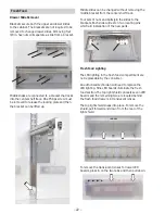
Unclip the HMI (User Interface) harness from the
left side of the housing. Note the routing for the
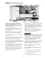
LED harness. When reinstalling the LED housing,
the harness will need to be routed as shown in the
image below to prevent pinching wires.
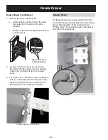
Disconnect the six-pin connector and remove two
Philips screws holding the damper bracket. The
bracket will need to be reused should the damper
be replaced. Once the bracket is removed, the
damper can be pulled from the cabinet.
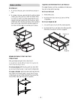
Upper and lower LED boards are mounted with two
plastic retainer pins. LED boards can be removed by
squeezing in on the sides of the pins, then pulling
down on the board and disconnecting the three pin
connector.
Diagnosing
LED boards receive both a 13 VDC switched (when a
door is opened) and 13 VDC constant voltages from
the main control board. Voltage can be checked at
the LED boards or at the main board.
LED Board:
• Black: Ground
• Red: Constant 13 VDC supply
• Yellow: Switched 13 VDC supply
Main Board:
• J4 pin 2 through J4 pin 3: Constant 13 VDC
supply
• J4 pin 3 through J5 pin 3: Switched 13 VDC
supply
$LUÀRZHQWHUVWKHIUHVKIRRGFRPSDUWPHQWWKURXJK
an electronic damper. The damper is located at the
top of the fresh food compartment behind the light
housing. The damper motor has an approximate
resistance of 415 ohms from the blue to white wires
and from the red to yellow wires.
Damper


