– 46 –
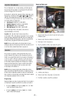
Inverter Removal
1. Disconnect the ground wire by removing one
Philips screw.
2. Disconnect the AC and DC connectors.
3. Remove 1/4 in. hex screw.
4. Tip the bottom of the inverter to the left.
5. Lift the inverter up.
6. Disconnect the compressor connector.
7. Pull the inverter out of the cabinet.
Inverter Compressor
The compressor is a reciprocating, variable speed,
4-pole type. It operates on 3-phase, 80 to 230 VAC
within a range of 57 to 104 Hz.
An inverter controls the speed of the compressor by
frequency variation and by Pulse Width Modulation
(PWM). Changing frequency and PWM will cause
DQHȺHFWLYHYROWDJHEHWZHHQDQG9$&WREH
received at the compressor.
• Low
Speed: 67.82 HZ = 1981 RPM
• Medium
Speed: 76.29 HZ = 2220 RPM
• High
Speed: 122.0 = 3780 RPM
• Startup
Speed: 55.49 HZ = 1620 RPM
Each winding of the compressor should be
approximately 12.4 ohms.
Caution: Do not attempt to direct-start the
compressor. The compressor operates on a 3-phase
power supply. Applying 120 VAC to the compressor
will permanently damage the unit. It is not possible
to start the compressor without an inverter.
NOTE: Some voltmeters will not be able to read
voltage output or frequency from the inverter and it
is not recommended that it be measured.
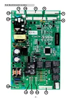
The inverter receives commands from the main
control board. The main control board will send a
PWM run signal from the J15 connector of between
9'&WR9'&HȺHFWLYHYROWDJHWRWKHLQYHUWHUDOO
wires must be connected). The inverter will select
compressor speed (voltage and frequency output)
based on this signal. The main control board will
only send a run signal to the inverter when the
compressor should be on.
NOTE: When measuring signal voltage (from the
main control board) at the inverter, a reading of 4 to
6 VDC will be measured with all wires connected. If
the inverter wiring is disconnected, the board output
will measure between 10 to 12 VDC.
Diagnosing
Signal voltage can be checked at the J15 connector
on the main board or at the DC inverter connector.
• J15 pin1 (white) to J15 pin 2 (red) = 10 - 12 VDC
when harness is disconnect
• J15 pin1 (white) to J15 pin 2 (red) = 4 - 6 VDC
with connected harness
Inverter


