3
SERIAL COMMUNICATION
The physical layer standards that are used for serial communications for SCADA purposes are:
●
EIA(RS)485 (often abbreviated to RS485)
●
K-Bus (a proprietary customization of RS485)
EIA(RS)232 is used for local communication with the IED (for transferring settings and downloading firmware
updates)
RS485 is similar to RS232 but for longer distances and it allows daisy-chaining and multi-dropping of IEDs.
K-Bus is a proprietary protocol quite similar to RS485, but it cannot be mixed on the same link as RS485.
Unlike RS485, K-Bus signals applied across two terminals are not polarised.
It is important to note that these are not data protocols. They only describe the physical characteristics
required for two devices to communicate with each other.
For a description of the K-Bus standard see
(on page 196) and Alstom Grid's K-Bus interface guide
reference R6509.
A full description of the RS485 is available in the published standard.
3.1
EIA(RS)232 BUS
The EIA(RS)232 interface uses the IEC 60870-5 FT1.2 frame format.
The IED supports an IEC 60870-5 FT1.2 connection on the front-port. This is intended for temporary local
connection and is not suitable for permanent connection. This interface uses a fixed baud rate of 19200 bps,
11-bit frame (8 data bits, 1 start bit, 1 stop bit, even parity bit), and a fixed device address of '1'.
EIA(RS)232 interfaces are polarised.
3.2
EIA(RS)485 BUS
The RS485 two-wire connection provides a half-duplex, fully isolated serial connection to the IED. The
connection is polarized but there is no agreed definition of which terminal is which. If the master is unable to
communicate with the product, and the communication parameters match, then it is possible that the two-
wire connection is reversed.
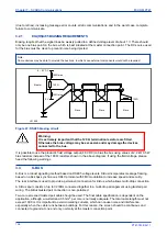
The RS485 bus must be terminated at each end with 120 Ω 0.5 W terminating resistors between the signal
wires.
The RS485 standard requires that each device be directly connected to the actual bus. Stubs and tees are
forbidden. Loop bus and Star topologies are not part of the RS485 standard and are also forbidden.
Two-core screened twisted pair cable should be used. The final cable specification is dependent on the
application, although a multi-strand 0.5 mm
2
per core is normally adequate. The total cable length must not
exceed 1000 m. It is important to avoid circulating currents, which can cause noise and interference,
especially when the cable runs between buildings. For this reason, the screen should be continuous and
connected to ground at one end only, normally at the master connection point.
The RS485 signal is a differential signal and there is no signal ground connection. If a signal ground
connection is present in the bus cable then it must be ignored. At no stage should this be connected to the
cable's screen or to the product’s chassis. This is for both safety and noise reasons.
It may be necessary to bias the signal wires to prevent jabber. Jabber occurs when the signal level has an
indeterminate state because the bus is not being actively driven. This can occur when all the slaves are in
receive mode and the master is slow to turn from receive mode to transmit mode. This may be because the
master is waiting in receive mode, in a high impedance state, until it has something to transmit. Jabber
causes the receiving device(s) to miss the first bits of the first character in the packet, which results in the
slave rejecting the message and consequently not responding. Symptoms of this are; poor response times
MiCOM P747
Chapter 7 - SCADA Communications
P747-TM-EN-1
195
P747-TM-EN-1.1
Содержание MiCOM P747 Agile
Страница 2: ......
Страница 16: ...Contents MiCOM P747 xiv P747 TM EN 1 P747 TM EN 1 1...
Страница 20: ...Table of Figures MiCOM P747 xviii P747 TM EN 1 P747 TM EN 1 1...
Страница 21: ...INTRODUCTION CHAPTER 1...
Страница 22: ...Chapter 1 Introduction MiCOM P747 2 P747 TM EN 1 P747 TM EN 1 1...
Страница 31: ...SAFETY INFORMATION CHAPTER 2...
Страница 32: ...Chapter 2 Safety Information MiCOM P747 12 P747 TM EN 1 P747 TM EN 1 1...
Страница 42: ...Chapter 2 Safety Information MiCOM P747 22 P747 TM EN 1 P747 TM EN 1 1...
Страница 43: ...HARDWARE DESIGN CHAPTER 3...
Страница 44: ...Chapter 3 Hardware Design MiCOM P747 24 P747 TM EN 1 P747 TM EN 1 1...
Страница 74: ...Chapter 3 Hardware Design MiCOM P747 54 P747 TM EN 1 P747 TM EN 1 1...
Страница 75: ...CONFIGURATION CHAPTER 4...
Страница 76: ...Chapter 4 Configuration MiCOM P747 56 P747 TM EN 1 P747 TM EN 1 1...
Страница 117: ...PROTECTION FUNCTIONS CHAPTER 5...
Страница 118: ...Chapter 5 Protection Functions MiCOM P747 98 P747 TM EN 1 P747 TM EN 1 1...
Страница 160: ...Chapter 5 Protection Functions MiCOM P747 140 P747 TM EN 1 P747 TM EN 1 1...
Страница 161: ...MONITORING AND CONTROL CHAPTER 6...
Страница 162: ...Chapter 6 Monitoring and Control MiCOM P747 142 P747 TM EN 1 P747 TM EN 1 1...
Страница 211: ...SCADA COMMUNICATIONS CHAPTER 7...
Страница 212: ...Chapter 7 SCADA Communications MiCOM P747 192 P747 TM EN 1 P747 TM EN 1 1...
Страница 259: ...REDUNDANT ETHERNET CHAPTER 8...
Страница 260: ...Chapter 8 Redundant Ethernet MiCOM P747 240 P747 TM EN 1 P747 TM EN 1 1...
Страница 293: ...CYBER SECURITY CHAPTER 9...
Страница 294: ...Chapter 9 Cyber Security MiCOM P747 274 P747 TM EN 1 P747 TM EN 1 1...
Страница 313: ...SETTINGS APPLICATION SOFTWARE CHAPTER 10...
Страница 314: ...Chapter 10 Settings Application Software MiCOM P747 294 P747 TM EN 1 P747 TM EN 1 1...
Страница 322: ...Chapter 10 Settings Application Software MiCOM P747 302 P747 TM EN 1 P747 TM EN 1 1...
Страница 323: ...BUSBAR COMMISSIONING TOOL CHAPTER 11...
Страница 324: ...Chapter 11 Busbar Commissioning Tool MiCOM P747 304 P747 TM EN 1 P747 TM EN 1 1...
Страница 330: ...Chapter 11 Busbar Commissioning Tool MiCOM P747 310 P747 TM EN 1 P747 TM EN 1 1...
Страница 331: ...SCHEME LOGIC CHAPTER 12...
Страница 332: ...Chapter 12 Scheme Logic MiCOM P747 312 P747 TM EN 1 P747 TM EN 1 1...
Страница 348: ...Chapter 12 Scheme Logic MiCOM P747 328 P747 TM EN 1 P747 TM EN 1 1...
Страница 349: ...INSTALLATION CHAPTER 13...
Страница 350: ...Chapter 13 Installation MiCOM P747 330 P747 TM EN 1 P747 TM EN 1 1...
Страница 361: ...COMMISSIONING INSTRUCTIONS CHAPTER 14...
Страница 362: ...Chapter 14 Commissioning Instructions MiCOM P747 342 P747 TM EN 1 P747 TM EN 1 1...
Страница 387: ...MAINTENANCE AND TROUBLESHOOTING CHAPTER 15...
Страница 388: ...Chapter 15 Maintenance and Troubleshooting MiCOM P747 368 P747 TM EN 1 P747 TM EN 1 1...
Страница 403: ...TECHNICAL SPECIFICATIONS CHAPTER 16...
Страница 404: ...Chapter 16 Technical Specifications MiCOM P747 384 P747 TM EN 1 P747 TM EN 1 1...
Страница 425: ...SYMBOLS AND GLOSSARY APPENDIX A...
Страница 426: ...Appendix A Symbols and Glossary MiCOM P747 406 P747 TM EN 1 P747 TM EN 1 1...
Страница 443: ...COMMISSIONING RECORD APPENDIX B...
Страница 444: ...Appendix B Commissioning Record MiCOM P747 424 P747 TM EN 1 P747 TM EN 1 1...
Страница 448: ...Final Checks Result LEDs reset Yes No Appendix B Commissioning Record MiCOM P747 428 P747 TM EN 1 P747 TM EN 1 1...
Страница 449: ...WIRING DIAGRAMS APPENDIX C...
Страница 450: ...Appendix C Wiring Diagrams MiCOM P747 430 P747 TM EN 1 P747 TM EN 1 1...
Страница 456: ...Appendix C Wiring Diagrams MiCOM P747 436 P747 TM EN 1 P747 TM EN 1 1...
Страница 457: ......


