background image

GEI-100268 

5

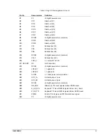
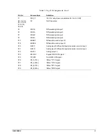
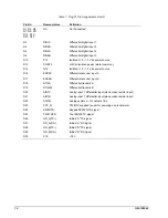
Table 2. Plug P2 Pin Assignments, Row B

Pin No.

Nomenclature

Definition

B1

P5

+5 digital power source

B2

XD1

Data bus (D1)

B3

XD5

Data bus (D5)

B4

XD9

Data bus (D9)

B5

XD13

Data bus (D13)

B6

XD17

Data bus (D17)

B7

XD21

Data bus (D21)

B8

DCOM

+5 digital power return (common)

B9

XD25

Data bus (D25)

B10

XD29

Data bus (D29)

B11

XA1

Address bus (A1)

B12

XA5

Address bus (A5)

B13

XA9

Address bus (A9)

B14

DCOM

+5 digital power return (common)

B15

XA13

Address bus (A13)

B16

0ACL_1

0 = route GR1 to ACL

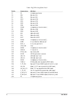
B17, B25-B27

NC

Not Connected

B18

DCOM

+5 digital power return (common)

B19

LDPLS1

1 = update I/O

B20

LDPLS2

1 = update I/O

B21

ACOM

+/- 15Vdc power return (common)

B22

HIFI_1A

Hi-Fidelity input, 1 pair

B23

HIFI_2B

Hi-Fidelity input, 2 pair

B24

DCOM

+5 digital power return (common)

B28

GR_2RX

ISBus (1,2) TTL level signals to/from DSPX board

B29

K_RX_ACL

Keyboard TTL level RS232 signals to/from ACL_ board

B30

K_RX_TTL

Keyboard TTL level RS232 signals to/from DSPX board

B31

PWM2

24 kHz, 10-bit duty-cycle PWM meter driver signal

B32

P5

+5 digital power source

Содержание IS200BAIAH B Series

Страница 1: ...lized and idle equipment along with credit for buybacks and trade ins Custom engineering so your equipment works exactly as you specify Critical and expedited services Leasing Rentals Demos In stock Ready to ship TAR certified secure asset solutions Expert team I Trust guarantee I 100 satisfaction All trademarks brand names and brands appearing herein are the property of their respective owners Fi...

Страница 2: ...strial Systems Indicates a procedure or condition that if not strictly observed could result in damage to or destruction of equipment Note Indicates an essential or important procedure or statement Table of Contents Functional Description 1 Application Data 2 Indicators 2 Testpoints and Jumpers 2 I O Connectors 2 Renewal Warranty Replacement 12 How to Order a Board 12 Board Identification 12 Warra...

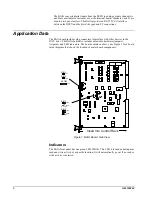
Страница 3: ...r devices in the IGCT drive The BAIA board also includes adjustable hardware jumpers testpoints and LED indicators The board contains no fuses See Figure 1 for a board layout diagram that shows the location of major board components Insert Into Control Rack AIN1 AIN2 TP1 TP2 ACOM TP3 JP5B AIN1 JP5A VIN 1 4 20 MA JP6B AIN2 JP6A VIN 1 4 20 MA Figure 1 BAIA Board Side View Indicators The BAIA front p...

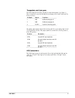
Страница 4: ...og input jumpers are provided in two pairs for a given analog input circuit A VIN and B 4 20 mA The jumper should be in either the 4 20 mA position or in the VIN position Function Description JP5A Lowers AIN1 input impedance JP5B Connects burden resistor across AIN1 input pair JP6A Lowers AIN2 input impedance JP6B Connects burden resistor across AIN2 input pair I O Connectors The BAIA board connec...

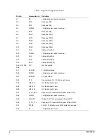
Страница 5: ...Address bus A8 A15 XA12 Address bus A12 A16 A18 A19 A26 NC Not Connected A17 0XCSIO 0 BAIA selected A20 DCOM 5 digital power return common A21 0RESET 0 reset BAIA A22 P15 Non isolated 15 15 Vdc power source A23 HIFI_2A Hi Fidelity input 2 pair A24 HIFI_4A Hi Fidelity input 4 pair A25 HIFI_4B Hi Fidelity input 4 pair A27 K_TX_ACL Keyboard TTL level RS232 signals to from ACL A28 DCOM 5 digital power...

Страница 6: ...return common B15 XA13 Address bus A13 B16 0ACL_1 0 route GR1 to ACL B17 B25 B27 NC Not Connected B18 DCOM 5 digital power return common B19 LDPLS1 1 update I O B20 LDPLS2 1 update I O B21 ACOM 15Vdc power return common B22 HIFI_1A Hi Fidelity input 1 pair B23 HIFI_2B Hi Fidelity input 2 pair B24 DCOM 5 digital power return common B28 GR_2RX ISBus 1 2 TTL level signals to from DSPX board B29 K_RX_...

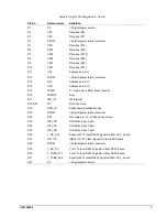
Страница 7: ...K1 Clock C18 DCOM 5 digital power return common C19 LDPLS3 1 Update I O C20 SYNC_LAN Synchronize LAN C21 ACOM 15Vdc power return common C22 HIFI_1B Hi Fidelity input 1 pair C23 HIFI_3A Hi Fidelity input 3 pair C24 DCOM 5 digital power return common C25 CLK20_1 20 MHz global clock supplied by DSPX board C26 T_TX_ACL Keyboard TTL level RS232 signals to from ACL_ board C27 GR_1RX ISBus 1 2 TTL level ...

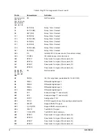
Страница 8: ...USY Busy D17 INT_IO I O interrupt D18 D21 NC Not Connected D19 BRD_ID Serial board identification line D20 DCOM 5 digital power return common D22 N15 Non isolated 15 15Vdc power source D23 HIFI_3B Hi Fidelity input 3 pair D24 HIFI_5A Hi Fidelity input 5 pair D25 HIFI_5B Hi Fidelity input 5 pair D26 T_RX_ACL Keyboard TTL level RS232 signals to from ACL_ board D27 GR_1TX ISBus 1 2 TTL level signals ...

Страница 9: ...urn N A31 MTR2P Panel meter 1 4 signal P and return N A32 MTR2N Panel meter 1 4 signal P and return N B1 B3 B5 B7 B9 B11 17 B19 B21 B28 NC Not Connected B2 SSR_N I24 V dc relay driver use isolated 24 V dc COM B4 DIN2A Differential digital input 2 B6 DIN3B Differential digital input 3 B8 DIN5A Differential digital input 5 B10 DIN6B Differential digital input 6 B18 EV1 Encoder voltage 1 and return 2...

Страница 10: ...l digital input 4 C9 DIN6A Differential digital input 6 C17 ENCBP Differential encoder input B C18 ENCBN Differential encoder input B C20 AIN2P Analog input 2 differential input also burden resistor input C21 AIN2N Analog input 2 differential input also burden resistor input C22 AOUT2 Analog output 2 C24 K232RX Keypad RS232 RX signal C25 T232RX Tool RS232 RX signal C26 GR_A TX ISBus A TX signal C2...

Страница 11: ...ower source D16 ENCAP Differential encoder input A D17 ENCAN Differential encoder input A D18 DT M Differential transmit A D19 DT MB Differential transmit B D20 AIN1P Analog input 1 differential input also burden resistor input D21 AIN1N Analog input 1 differential input also burden resistor input D22 ACOM Analog common for outputs 1 2 D23 POT_N P12 N12 supplied to user for powering a potentiomete...

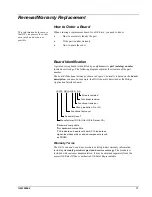
Страница 12: ...y is based on the board description or name For example the BAIA board is described as the Bridge Application Interface board IS 200 GBIA H A A A 1 Backward compatible 2Not backward compatible 3 200 indicates a base level board 215 indicates a higher level assembly or added components such as PROM Manufacturer DS IS for GE in Salem VA Assembly level3 Functional acronym Group variation G or H Funct...

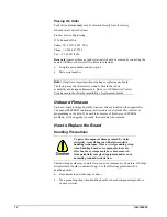
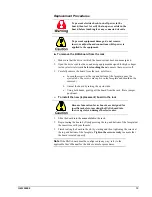
Страница 13: ...ped with the firmware already installed when applicable The onboard EEPROM containing this firmware is not intended for removal or programming in the field If a board fails because of firmware or EEPROM problems or if an upgrade is needed the board must be replaced How to Replace the Board Handling Precautions To prevent component damage caused by static electricity treat all boards with static se...

Страница 14: ...te near the ejector tabs The screws are captive in the faceplate and should not be removed b Unseat the board by raising the ejector tabs c Using both hands gently pull the board from the rack Note jumper positions To install the new replacement board in the rack Because Innovation Series boards are designed for specific rack slots inserting the BAIA board into the wrong slot can damage the electr...

Страница 15: ...14 GEI 100268 Notes g GE Industrial Systems General Electric Company 1501 Roanoke Blvd Salem VA 24153 6492 USA Issue date 1999 07 27 1998 by General Electric Company USA All rights reserved ...

Страница 16: ...quipment Have surplus equipment taking up shelf space We ll give it a new home Learn more Visit us at artisantg com for more info on price quotes drivers technical specifications manuals and documentation Artisan Scientific Corporation dba Artisan Technology Group is not an affiliate representative or authorized distributor for any manufacturer listed herein We re here to make your life easier How...

Отзывы: