10
GEI-100268
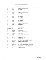
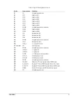
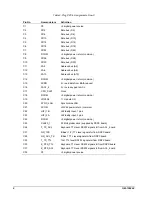
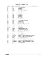
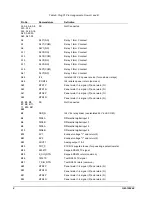
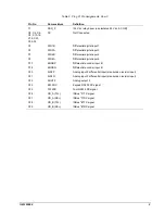
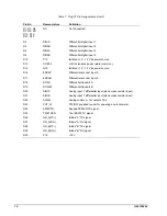
Table 7. Plug P1 Pin Assignments, Row D
Pin No.
Nomenclature
Definition
D1, D3, D5,
D7, D9, D11,
D13, D15,
D31, D32
NC
Not Connected
D2
DIN1A
Differential digital input 1
D4
DIN2B
Differential digital input 2
D6
DIN4A
Differential digital input 4
D8
DIN5B
Differential digital input 5
D10
P12
Is12,
−
12 V dc power source
D12
COM12
±
12Vdc isolated power return (common)
D14
N12
Is12,
−
12 V dc power source
D16
ENCAP
Differential encoder input A
D17
ENCAN
Differential encoder input A
D18
DT(M)
Differential transmit A
D19
DT(MB)
Differential transmit B
D20
AIN1P
Analog input 1 differential input (also burden resistor input)
D21
AIN1N
Analog input 1 differential input (also burden resistor input)
D22
ACOM
Analog common – for outputs 1 & 2
D23
POT_N
P12/N12 supplied to user for powering a potentiometer
D24
K232RTS
Keypad RS232 RTS signal
D25
T232TXEN
Tool RS232 TX signal
D26
GR_A(TX–)
ISBus "A" TX signal
D27
GR_A(RX–)
ISBus "A" RX signal
D28
GR_B(TX–)
ISBus "B" TX signal
D29
GR_B(RX–)
ISBus "B" RX signal
D30
P18
+18 V


