28 IPN250RTM
Publication No. IPN250RTM-HRM/2
3.2 LEDs
LINK
Refer to
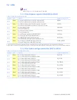
3.2.1 Miscellaneous signals LEDs (DS20 to DS26)
3.2.2 PCIe Switch configuration LEDs (DS27 to DS33)
Table 3-3 Miscellaneous Signals LEDs
Number Color
Function
Signal Connected To
DS20
Yellow
On = All non-volatile memory in system write-enabled
a
Off = All non-volatile memory in system write-protected
NVMRO
DS21
Yellow
On = IPN250 associated with this RTM is System Controller
b
Off = IPN250 associated with this RTM is not System Controller
SYSCON~
DS22
Yellow
On = TESTMODE is active
Off = Normal operation
TESTMODE
DS23
Yellow
On = GPU set for JTAG operation
Off = Normal operation
JTAG-GPU~
DS24
Yellow
On = HDMI output selected (on IPN250RTMB J2)
Off = DVI output selected (on IPN250RTMB J7)
HDMI_SEL~
DS25
Yellow
On = IPN250 has Firmware Hub Boot active
Off = IPN250 does not have Firmware Hub Boot active
BOOT_FWH~
DS26
Yellow
On = COM ports on IPN250 front panel are active
Off = Rear COM ports (on IPN250RTM) are active
COM12_FRONT~
a. May not reflect the setting of the corresponding DIP switch on the IPN250RTM if non-volatile memory has been write-enabled elsewhere in the system.
b.May not reflect the setting of the corresponding DIP switch on the IPN250RTM if the associated IPN250 has been made System Controller via the backplane or FABRTMP1.
Table 3-4 PCIe Switch Configuration LEDs
Number Color
Function
Signal Connected To
DS27
Yellow
On = Corresponding switch/link open
Off = Corresponding switch closed/pins linked
EP_PCFG1
DS28
Yellow
On = Corresponding switch/link open
Off = Corresponding switch closed/pins linked
EP_PCFG0~
DS29
Yellow
On = Corresponding switch closed/pins linked
Off = Corresponding switch/link open
NT_ENABLE~
DS30
Yellow
On = Corresponding switch/link open
Off = Corresponding switch closed/pins linked
NT_UPORT4
DS31
Yellow
On = Corresponding switch/link open
Off = Corresponding switch closed/pins linked
NT_UPORT2
DS32
Yellow
On = Corresponding switch/link open
Off = Corresponding switch closed/pins linked
NT_UPORT1
DS33
Yellow
On = Corresponding switch/link open
Off = Corresponding switch closed/pins linked
NT_UPORT0
Содержание IPN250RTM
Страница 1: ...Hardware Reference Manual IPN250RTM Edition 2 Publication No IPN250RTM HRM 2 GE Intelligent Platforms ...
Страница 10: ...10 IPN250RTM Publication No IPN250RTM HRM 2 Figure 1 2 IPN250RTMB ...
Страница 11: ...Publication No IPN250RTM HRM 2 IPN250RTM 11 Figure 1 3 IPN250RTMA and IPN250RTMB Assembly ...

