Publication No. IPN250RTM-HRM/2
Connectors 21
2.4 IPN250RTMB
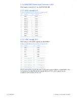
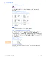
2.4.1 HDMI Connector (J2)
LINK
See the
section.
The
IPN250RTM
only
supports
the
mini
‐
HDMI
connector
(HDMI
Type
C
connector).
NOTE
This connector is not available for use on the Rev 1 IPN250RTM.
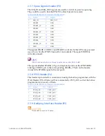
2.4.2 TV Capture Connectors (J3 to J6)
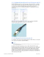
The
IPN250
supports
capture
of
video
from
up
to
four
TV
‐
format
video
sources.
These
can
be
connected
to
four
SSMB
connectors
on
the
IPN250RTM.
J3
is
accessible
via
the
front
panel
of
the
IPN250RTM,
and
can
be
used
for
testing
basic
operation
of
the
TV
capture
device.
J4
to
J6
are
fitted
in
‐
board
and
are
most
likely
to
be
used
during
design
validation
of
the
IPN250.
The
SSMB
connectors
route
the
TV
signals
as
follows:
GEIP
offers
cable
ARACC
‐
3BNCSSMB1,
which
is
a
1.9m
long
SSMB
to
BNC
adaptor
cable.
Table 2-11 IPN250RTMB J2 Pin Assignments
Pin
Signal
Pin
Signal
1
GND
2
HDMI_DVI_TX2P
3
HDMI_DVI_TX2N
4
GND
5
HDMI_DVI_TX1P
6
HDMI_DVI_TX1N
7
GND
8
HDMI_DVI_TX0P
9
HDMI_DVI_TX0N
10
GND
11
HDMI_DVI_CLKP
12
HDMI_DVI_CLKN
13
GND
14
Unconnected
15
DDC2_CLOCK
16
DDC2_DATA
17
Unconnected
18
DDC2_5V
19
HOTPLUG2
Table 2-12 TV Capture Connectors
Connector
Signal
J3
CVBS2_C1_Pb
J4
CVBS3_C2
J5
CVBS1_Y1
J6
CVBS4_Y2_Pr
Errata
February
2011
Содержание IPN250RTM
Страница 1: ...Hardware Reference Manual IPN250RTM Edition 2 Publication No IPN250RTM HRM 2 GE Intelligent Platforms ...
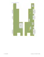
Страница 10: ...10 IPN250RTM Publication No IPN250RTM HRM 2 Figure 1 2 IPN250RTMB ...
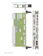
Страница 11: ...Publication No IPN250RTM HRM 2 IPN250RTM 11 Figure 1 3 IPN250RTMA and IPN250RTMB Assembly ...


