Publication No. IPN250RTM-HRM/2
Connectors 23
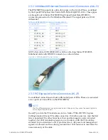
2.4.4 GPU DVI-Dual Link Connector (J8)
LINK
See the
for further information.
The
IPN250RTM
supports
Dual
Link
DVI
‐
I
from
one
of
the
GPU
heads
on
the
IPN250.
This
connector
can
be
used
for
Single
Link
DVI,
Dual
Link
DVI
or
analog
VGA
RGB,
all
from
the
same
head
of
the
GPU.
Only
one
format
is
active
at
a
time
and
is
determined
by
the
GPU,
depending
on
the
type
of
monitor
connected
to
this
connector.
GEIP
offers
cable
C
‐
CBL000224
‐
001,
which
is
a
2m
long
StarTech
DVIIDMM6
DVI
‐
I
dual
link
cable
with
male
connectors.
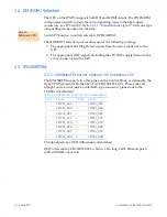
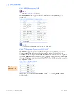
2.4.5 USB0/1 Connectors (J10/ J9)
The
signal
pairs
are
90
differential.
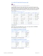
2.4.6 USB2/3 Connectors (J11/ J12)
The
signal
pairs
are
90
differential.
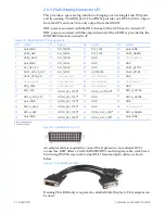
Table 2-14 IPN250RTMB J8 Pin Assignments
Pin
Signal
Pin
Signal
Pin
Signal
Pin
Signal
1
DVI_DL_TX2N
b
9
DVI_DL_TX1N
b
17
DVI_DL_TX0N
b
A1
VGA1_GREEN
2
DVI_DL_TX2P
b
10
DVI_DL_TX1P
b
18
DVI_DL_TX0P
b
A2
VGA1_RED
a
a. Routed over Quiet GND.
3
GND
11
GND
19
GND
A3
VGA1_BLUE
a
4
DVI_DL_TX4N
b
12
DVI_DL_TX3N
b
20
DVI_DL_TX5N
b
A4
VGA1_HSYNC
5
DVI_DL_TX4P
b
13
DVI_DL_TX3P
b
21
DVI_DL_TX5P
b
SH1
Quiet GND
6
DDC1_CLOCK
14
DDC1_5V
22
GND
7
DDC1_DATA
15
Quiet GND
23
DVI_DL_CLKP
b
b. 90
differential pairs.
8
VGA1_VSYNC
16
HOTPLUG1
24
DVI_DL_CLKN
b
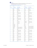
Table 2-1 IPN250RTMA J10, J9 Connector Pin Assignments
J10 Pin
Signal
J9 Pin
Signal
1
P5V_USBP0
1
P5V_USBP1
2
USB0_DN
2
USB1_DN
3
USB0_DP
3
USB1_DP
4
GND
4
GND
Table 2-1 IPN250RTMA J11, J12 Connector Pin Assignments
J11 Pin
Signal
J12 Pin
Signal
1
P5V_USBP2
1
P5V_USBP3
2
USB2_DN
2
USB3_DN
3
USB2_DP
3
USB3_DP
4
GND
4
GND
Содержание IPN250RTM
Страница 1: ...Hardware Reference Manual IPN250RTM Edition 2 Publication No IPN250RTM HRM 2 GE Intelligent Platforms ...
Страница 10: ...10 IPN250RTM Publication No IPN250RTM HRM 2 Figure 1 2 IPN250RTMB ...
Страница 11: ...Publication No IPN250RTM HRM 2 IPN250RTM 11 Figure 1 3 IPN250RTMA and IPN250RTMB Assembly ...

