GE Interlogix FP1500 Скачать руководство пользователя страница 53


FP1500 Installation, Configuration and Commissioning Manual 

51


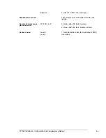
Auxiliary 24 V output: 


Between 18 and 28 VDC, 250 mA; nominal 24 
VDC 


Recommended cable: 

KAL21: 
Stranded 2-wire cable 1.5 mm² 
Conductor resistance: 

 13.3 

 / Km 

Working temperature: -20

°

C to +70

°

C  


Serial ports: 

Number of serial ports:  


Port 1 RS232 


Port 2 RS485 (optional). Galvanic isolation 
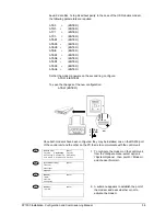
 

RS232 

Maximum Length 15m 


Baud rate: 9600 Baud 


Recommended cable  
3-wire cable 1 mm² stranded and shielded 
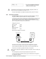
 

RS485 

Maximum Length: 1200m  


 Recommended 

cable 

1.5 mm² stranded cable, screening 
recommended 


Baud rate: 9600 Baud 


End-of-line resistances: 150 ohm. 


Recommended cable: 

KAL21A: 
2 wire cable 1.5 mm² stranded and shielded 
Impedance: 115 


Maximum voltage: 1500 V 
Isolating resistance: > 10,000 

 / Km 

Conductor resistance: 

 13.3 

 / Km 

Working temperature: -20

°

C to +85

°

Power supply 

Mains voltage: 

230 VAC 50 Hz 


110 VAC 60 Hz 


Voltage tolerance: 


+ 10%  - 15% 


Power supply input:  

24 VAC 


Power fuses: 


Mains fuse for 230 VAC: F12 1A (T) 250V 


Mains fuse for 110 VAC: F11 2A (T) 250V 


Mains input fuse (F3) 1: 3A (T) 20 mm HCR 


Auxiliary 24 VDC fuse (F1): 0.3A (T) 20 mm HRC 


Battery fuse (F2): 3A (T) 20 mm HCR 


Consumption on 
standby: 

FP1500/2:  

Control unit 175 mA 


Loop with 125+125 elements 35 mA x 2= 70 mA 


Option of 24 VDC Aux 300 mA. 


Current on alarm: 

FP1500/2: 

Control unit 240 mA 


Loop with 125+125 elements 35 mA x 2= 70 mA 


Option of 24 VDC Aux 300 mA 


Option of sounders output 500 mA 


Battery charger 

Voltage output: 

27.6 VDC nominal at 20°C 


Compensation: -3 

mV/ºC 


Load current: 

350 mA 

Содержание Interlogix FP1500

Страница 1: ...Analogue Addressable Fire Panels FP1500 Manual for Installation Configuration and Commissioning Version 2 1 November 2003 ...

Страница 2: ...p www geindustrial com ge interlogix emea 2003 GE Interlogix B V All rights reserved GE Interlogix B V grants the right to reprint this manual for internal use only GE Interlogix B V reserves the right to change information without notice ...

Страница 3: ...elements 19 4 System configuration 21 4 1 Basic configuration 21 4 1 1 General parameters 22 4 1 2 Setting the Time and Date 23 4 1 3 Configuring a loop 24 4 1 4 Configuring a zone 25 4 1 5 Configuring elements 26 4 1 6 Configuring sounder outputs 28 4 1 7 Configuring relay outputs 30 4 2 Configuration with advanced options 31 4 2 1 Day mode setting 31 4 2 2 Sensitivity setting 32 4 2 3 Configurat...

Страница 4: ...lation Configuration and Commissioning Manual 2 5 4 6 Supply faults 46 5 4 7 Low battery 46 5 4 8 Others 46 6 Maintenance 47 7 Technical specifications 50 8 Applicable standards 53 9 Appendix Addresses of modules 54 ...

Страница 5: ...icable local authority laws or requirements To avoid potential problems and accidents carefully read this manual before starting the installation 1 1 Contents of the package It is important to verify the contents of the package Carefully check all the elements and verify that they are in perfect condition If not return the panel to the supplier in its original packing Figure 1 Contents of the pack...

Страница 6: ...f the installation without having to reconfigure the system Sensors and analogue input modules may be connected to the loop to collect information and warn of any risk situation In the event of an alarm the panel activates the output modules sounders and relays Each of the devices occupies a unique address and therefore are easily identified and managed independently The maximum cable length is 2 ...

Страница 7: ... cable is recommended Cable with a minimum section of 1 5 mm and 250 VAC cable is recommended The cable length must not be longer than 2 km The fire panel must be connected to an external bipolar magneto thermal switch Do not work on any connections without first disconnecting the external magneto thermal switch Do not use the mains fuse to cut the power supply BIPOLAR MAGNETO THERMAL SWITCH RELAY...

Страница 8: ...its of the fire panel The proper way of supplying current to the panel is First connect the mains magneto thermal switch 110 VAC or 230 VAC and then connect the batteries Not following this procedure may cause a small discharge and damage the system Once the installation is complete use a tester to ensure that there are no short circuits in the lines before connecting the mains ...

Страница 9: ...12 13 14 15 16 17 18 19 20 21 22 23 24 4 1 Liquid crystal display 2 Alarm zone LED 3 Zone numbering 4 Fault Disable Test zone LED 5 Service LED 6 General alarm LED 7 General fault LED 8 General disable LED 9 General test LED 10 Triggering of sirens LED and key 11 Silence sounders LED and key 12 Reset 13 Silence Buzzer LED and key 14 Evacuation LED and key 15 Multi language inserts 16 Out of servic...

Страница 10: ...on codes Following EN54 2 1997 the FP1500 fire panels have different access levels for security The configuration and control menus can be accessed only if the applicable code is entered Level 1 All the panel indications are operational but only visual access of the fire panel is allowed to verify that everything is working properly All controls are blocked No code is required to access this level...

Страница 11: ...configuring from the fire panel menu or through an external PC with the configuration software Auto search option to automatically identify all the addressed elements connected Operator indicator LEDs facilitate quick visual control of the state of the fire panel Event log that records all the events detected by the fire panel Capacity for 125 analogue addressable sensors 125 analogue modules Two ...

Страница 12: ...g to the wall Appropriate drill bits plugs and screws for the type and thickness of the wall where the fire panel is to be mounted is needed For configuring FP1500 panels and analogue sensors The PG700 Sensor Programmer is a portable unit for assigning addresses to 1500 Series sensors This unit has two operating modes Mode 1 Permits viewing the address of the detector by inserting it into the sock...

Страница 13: ...d screws to hold it Installation steps 1 Place the metal box on the wall orientate it correctly with the help of the level and mark with a pencil the position of the 3 or 4 screws 2 Remove the box from the wall and drill the holes and place the plugs 3 Place the fire panel on the wall and attach it with the right screws Do not use the fire panel metal box as a guide for the drill Before fixing the...

Страница 14: ... the cables to the housing is highly recommended If the system is exposed to an electromagnetic environment the use of ferrite as close as possible to the connection is recommended See drawing Once the fire panel is mounted on the wall the connections can be started The loops the mains and the additional elements are connected to the main board through the holes on the top The hole located away fr...

Страница 15: ...pply The mains fuse must be changed depending on the voltage For a 110 VAC power source insert the fuse into the left fuse holder For a 230 VAC power supply insert the fuse into the right fuse holder See section 7 Technical specifications for fuse locations and characteristics Do not use the mains fuse for connecting and disconnecting the fire panel from the mains Use the bipolar magneto thermal s...

Страница 16: ...avoid external interference See section 7 Technical specifications for full cable recommendations The maximum length of the loop is 2 km The resistance of the loop cable must be less than 44 Ohm and the maximum capacitance of the line must be less than 500 nF Connect each detector and module to the loop along the cable run See sections 3 5 4 and 3 5 7 Once the loop has been installed connect it to...

Страница 17: ... return wires to R and R The colouring of the cables helps to distinguish between and Connect the ground cable or shield to the ground terminal Be careful to connect only one of the ends either the output O or the return R one It is important to have continuity in the shield at each of the connections of the loop ...

Страница 18: ...es a physical address on the loop from 1 to 125 The number of sensors installed on a loop must be in accordance with local regulations It is recommended that you carefully read the technical specifications and the assembly and installation manuals included in the packing of every product Sensitive to smoke DI1552 Operates by the imbalance of its ionisation chambers in the presence of smoke DP1551 ...

Страница 19: ...the fire panel keypad Lastly mount the detector in the base Figure 10 Connection of the loop connector strip from the base plate 3 5 5 Connecting modules The modules are elements connected to the loop that handle the system s input and output information Up to 125 modules can be installed on a loop with each occupying a logical address from 128 to 252 Some of the modules need additional external p...

Страница 20: ... are as follows 1 Install the cable connecting any polarized siren or with a corresponding diode as required without exceeding 300 mA 2 Place a 4K7 W end of line resistance in last siren 3 Connect the circuit to the control unit through the terminals on the main board identified as SND1 and SND1 Figure 12 Connection of supervised sirens to the base of the main board Use polarized sounders or insta...

Страница 21: ...In the FP1500 control unit the only optional element is the RS485 which requires the corresponding IC KAL785 701 When installing the optional elements the panel must be disconnected from the power supply Disconnect the external magneto thermal switch and the batteries before inserting the IC For the RS485 connections you must use cable that is stranded Screening is recommended The FP1500 has two s...

Страница 22: ... that the PINS on the IC are in good condition and unbent 3 Insert the IC into the correct position in the slot 4 Ensure the correct position of all the pins on the IC Slot on main board for KA785 701 chip KAL 785 701 The chip has an installation position Check position ...

Страница 23: ... FP1500 system has been configured and all its elements have been installed the commissioning process begins This configuration enables each element to be identified and carry out its function appropriately in the system 4 1 Basic configuration When the system is connected for the first time the control unit does not detect any of the connected elements The configuration is carried out through scr...

Страница 24: ...t screen access option 1 Configure CONFIGURE Exit 1 System 4 System Op 7 Events 2 See Config 5 Check Prog 8 Day Mode 3 Time Date 6 Power supply 9 Codes If you are asked the code again enter 9898 Select option 4 System Options Here you can programme the parameters SYSTEM OPTIONS Exit 1 General 2 Messages 3 Modem Language SPANISH Calibration time 00 00 LED Flashing YES Historic Mode NORMAL 1 General...

Страница 25: ...he case of a network of control units you must give each one a different value Remote Reset This option lets you configure the SND2 sirens output as a remote RESET input If the terminals of the SND2 is short circuited whit this option configured the system RESETS This option must be restricted to access level 2 Installation reference Upper case letters and numbers 2 Messages Once configured and fu...

Страница 26: ...the configure menu select option 1 SYSTEM 3 A menu appears with all the configurable elements In this case select option 1 Loop1 SYSTEM Exit 1 Loop 1 4 Loop 4 7 Sirens 2 Loop 2 5 Loop 5 8 Relays 3 Loop 3 6 Peripherals 9 PC Loop 1 Exit 1 Zones 4 Calibrate 2 Elements 5 Prog Dir 3 Auto search Searching The menu only allows access to the loops that are physically connected to the control unit 4 In the...

Страница 27: ...vices of Loop 01 From the address 000 To the address 255 Are in Zone 001 This screen indicates the addresses of all the elements in this zone E g The devices of Loop 1 with addresses between 001 and 255 are in zone 001 To change the values use the arrow keys to go to the text to be modified The text flashes and the new data may be supplied When the new values have been inserted confirm with the EN...

Страница 28: ...dress 001 Text Room 1005 Type Ionic Analog Value 16 Event 018 Loop 01 Zone 001 Address 001 Text Room 1005 Type Ionic Analog Value 16 Event 018 To make changes to the configuration of the element press the 9 key A menu appears showing the fields that can be changed depending on the device type If you press the operation is cancelled and the screen returns to the previous menu 1 Sensor Text 2 Zone 3...

Страница 29: ...of introducing text that is frequently repeated for many locations The control unit has a series of pre programmed words that can be selected using the 9 key to advance down the list E g To change a word Room to a different one Corridor select the Words Mode and delete the word with the BACK key The cursor remains in position ready for the introduction of the new text To enter the word CORRIDOR pr...

Страница 30: ...onnected directly to the loop or through sounder modules Sounder modules and loop sounders use the address segment of the modules from 128 to 252 The siren configuration is the same for both methods Once the auto search has been carried out on the devices on the loop by default the system allocates the activation of all the sirens immediately for any fire alarm in any zone Each output can be alloc...

Страница 31: ...e allocated zones e g from 1 to 12 LOGIC LINE 1 ZONE MODE 001 TO 012 10 sec DELAY c DELAY The output activates with a 10 second delay after the fire has been detected e g from 1 to 12 The delay times are adjustable in multiples of 10 up to 600 seconds This is only applicable to the relay outputs of the main board R1 and R2 loop sirens and SND1 and SND2 LOGIC LINE 1 ZONE MODE 001 TO 012 10 sec PULS...

Страница 32: ...figuration displayed on the screen comes into effect when ENTER is pressed To cancel press All the PULSING actions are only applicable to the loop and main board outputs 4 1 7 Configuring relay outputs The relays are configured in the same way as the sirens with a few exceptions The main board relays may be configured to trigger with the Trigger sirens key activating the option With evacuation Yes...

Страница 33: ...n with advanced options 4 2 1 Day mode setting The control unit can be pre programmed to operate in certain ways at certain times of the day Delayed day mode The control unit can be configured to delay the triggering of outputs in any zone During the allocated delay period the control unit receives an alarm warning A complete fire condition is executed if no action is executed in a time specified ...

Страница 34: ... alarm and alarm thresholds of any detector Indicating the start and end time we allocate new values during periods of the day when we wish to vary the default thresholds allocated in the factory This gives the sensors greater or lower sensitivity depending on the zone in which they are located and the activity carried out in the zone in which they act Configuration day mode sensitivity CONFIGURE ...

Страница 35: ...rst and last control units Once the control units are connected with their system installed they must be configured to form part of the network Proceed as follows MAIN MENU Exit 1 Configure 4 Connect 7 See 2 Test 5 Disconnect 3 Time 6 Print You must define a unique address for each of the control units From the Main Menu access option 1 Configuration and in this option option 4 System Options CONF...

Страница 36: ...units Share Zones Each control unit can define up to 40 zones FP1500 This option makes it possible for the control units to share the same zones or for each one to have its own Global events By default all the control units connected on the network send the events to the rest of the control units Each of them must accept or reject this function in accord with the chosen option YES or NO If YES is ...

Страница 37: ...and language of the FP1500R repeaters Once the address has been set perform the auto search for peripherals from the master control unit to configure all the elements installed on the network through the RS485 port Figure 16 FR1500 repeater Figure 17 Repeater to control unit connection diagram 4 2 5 Connection of a modem The analogue fire detection system allows the connection of a GSM modem This ...

Страница 38: ...RINT Exit 1 Element 4 Disconnected 2 Historic 5 Options 3 Mode Printer Mode OFF CONFIGURE Exit 1 System 4 System Op 7 Events 2 See Config 5 Check Prog 8 Day Mode 3 Time Date 6 Power Supply 9 Codes SYSTEM OPTIONS Exit 1 General 2 Messages 3 Modem MODEM Exit 1 GSM 2 Normal 3 Telephones For the installation of the GSM modem 1 Connect the modem serial cable to the RS232 port of the control unit 2 Conn...

Страница 39: ... Fault telephone Upper case letters and numbers In option 1 Faults allocate the telephone number to be alerted in the case of faults Alarm telephone Upper case letters and numbers In option 2 Alarms the number that must communicate in case of alarm Connection to conventional modem The analogue fire detection system enables the connection of a conventional modem to establish occasional communicatio...

Страница 40: ...th modems have been configured they may be installed one on the RS232 port of the control unit and the other on the PC that is to communicate with the control unit CONFIGURE Exit 1 System 4 System Op 7 Events 2 See Config 5 Check Prog 8 Day Mode 3 Time Date 6 Power Supply 9 Codes 1 To configure the modem on the control unit from the configure menu select option 4 System Options then point 3 Modem ...

Страница 41: ...erter module to the PC The converter modules must have their own configuration software installed and configured with the following RS232 serial port communication data Configure the serial port Bits per second 9 600 Bits of data 8 bits Parity None Parity bits Stop bit 1 Flow control None Set up a local IP address and a remote IP Communicate the analogue control unit with the configuration program...

Страница 42: ... computer The connection of a FP1500 analogue control panel to a computer must be done through RS232 and an RS232 card must be installed in one of the serial ports In the FP1500 you must use port 1 RS1 Requirements If graphics software is used 1 Identify the control unit as Master See section 4 2 3 2 Give the control unit an address See section 4 4 1 3 Perform an auto search for peripherals See se...

Страница 43: ...ns 3 Mode Exit 5 Options From PRINT select option 3 Mode Adjust the printing mode with the 9 key Printer Mode Manual Manual Prints only when the user requires Auto Automatically prints alarms or faults as they occur OFF The printer is disabled 4 2 10 Changing the access level codes The level 3 access code for the control unit 9898 factory setting may be changed As with level 2 codes up to 10 diffe...

Страница 44: ... only one code exists The control unit has the code 9898 factory setting but this can be changed ENTER the control unit requires the current code and then you may type in the new code The code is changed from this moment on Write down your access code and save it in a safe place 4 3 Graphics software The FP1500 analogue fire detection system has additional software that enables the management and ...

Страница 45: ...rs See section 3 4 4 Check that the RS485 lines if used have the 150 Ohm resistance at the ends Check the correct installation of all the elements See section 3 4 3 to 3 4 7 Review the optional components cards memories etc See section 3 5 Check that there are no short circuits between the Auxiliary 24 VDC output and the loop communication lines 5 2 System power up An external bipolar magneto ther...

Страница 46: ...e implanted configuration 5 4 Troubleshooting guide 5 4 1 Earth faults The system detects if a current leakage to earth occurs The FP1500 indicates this through the Earth Fault LED Even though this does not normally adversely affect the operation of the system this fault needs to be resolved as soon as possible A problem involving leakage to earth adversely affects the ability of the system to han...

Страница 47: ...same address Not all the connected elements have been detected Steps to follow to re address elements Once the configuration has finalized the control unit displays the total of the connected elements If any of them has not been detected or if two or more elements share the same address they do not appear in the total sum Perform the auto search again to ensure that the problem exists and that it ...

Страница 48: ...4 7 Low battery The voltage of the batteries may be low With the control unit powered by batteries only check that the voltage is above 24V Check that the fuse of the batteries on the main board is in correct working order Check that the output voltage of the batteries is 27 6V when the control unit is connected to the mains without batteries If the batteries are in bad condition losing liquid the...

Страница 49: ...cords of the control unit implementing the appropriate corrective actions as required 2 Examine all the battery connections and the voltage 3 In each zone check the alarm fault and auxiliary functions of the control and signalling equipment 4 Visual inspection of the control and signalling equipment to detect a possible increase in humidity or any other type of deterioration 5 Check if there has b...

Страница 50: ...FP1500 Installation Configuration and Commissioning Manual 48 Batteries Even though the batteries test OK it is recommended they be changed every four years ...

Страница 51: ...an manufacturer Above 10 years Recommended replacement 10 years in a control unit in continual service Every 4 years for the circuits of a replacement microprocessor that have not been connected to the power supply Alphanumeric liquid crystal screen Expected lifespan manufacturer Above 10 years Recommended replacement When the screen cannot read easily The liquid crystal screen with LED lighting h...

Страница 52: ...oop length 2 km Maximum loop resistance 44 Ohm Maximum loop capacity 500 nF Recommended cable KAL21A 2 wire cable 1 5 mm stranded and shielded Impedance 115 Ω Maximum voltage 1500 V Isolating resistance 10000 Ω Km Conductor resistance 13 3 Ω Km Working temperature 20 C to 85 C Baud Rate 1024 Baud Communication protocol Proprietary Sounder output Number of outputs on main board 2 configurable outpu...

Страница 53: ...stranded and shielded Impedance 115 Ω Maximum voltage 1500 V Isolating resistance 10 000 Ω Km Conductor resistance 13 3 Ω Km Working temperature 20 C to 85 C Power supply Mains voltage 230 VAC 50 Hz 110 VAC 60 Hz Voltage tolerance 10 15 Power supply input 24 VAC Power fuses Mains fuse for 230 VAC F12 1A T 250V Mains fuse for 110 VAC F11 2A T 250V Mains input fuse F3 1 3A T 20 mm HCR Auxiliary 24 V...

Страница 54: ... lead type Alphanumeric screen LCD screen 4 lines x 40 characters with back lighting Number of alarm zones per control unit FP1500 1 2 20 zones with LED alarm indicator 20 zones with LED fault disable indicator Access codes Level 2 10 user definable codes factory setting of 0000 Level 3 Code 9898 ...

Страница 55: ...alarm device output Auxiliary functions not required in the EN54 2 4 Apart from the compulsory and optional functions with requirements defined in the EN54 2 4 the FP1500 range incorporate auxiliary functions not required by the standard designed to enable the control and understanding of the system Auto search options Allocation of 10 different codes for access level 2 Possibility of configuratio...

Страница 56: ... 8 ON 160 1 2 3 4 5 6 7 8 ON 161 1 2 3 4 5 6 7 8 ON 162 1 2 3 4 5 6 7 8 ON 163 1 2 3 4 5 6 7 8 ON 164 1 2 3 4 5 6 7 8 ON 165 1 2 3 4 5 6 7 8 ON 166 1 2 3 4 5 6 7 8 ON 167 1 2 3 4 5 6 7 8 ON 168 1 2 3 4 5 6 7 8 ON 169 1 2 3 4 5 6 7 8 ON 170 1 2 3 4 5 6 7 8 ON 171 1 2 3 4 5 6 7 8 ON 172 1 2 3 4 5 6 7 8 ON 173 1 2 3 4 5 6 7 8 ON 174 1 2 3 4 5 6 7 8 ON 175 1 2 3 4 5 6 7 8 ON 176 1 2 3 4 5 6 7 8 ON 177...

Страница 57: ...N 218 1 2 3 4 5 6 7 8 ON 225 1 2 3 4 5 6 7 8 ON 226 1 2 3 4 5 6 7 8 ON 227 1 2 3 4 5 6 7 8 ON 228 1 2 3 4 5 6 7 8 ON 229 1 2 3 4 5 6 7 8 ON 224 1 2 3 4 5 6 7 8 ON 231 1 2 3 4 5 6 7 8 ON 232 1 2 3 4 5 6 7 8 ON 233 1 2 3 4 5 6 7 8 ON 234 1 2 3 4 5 6 7 8 ON 235 1 2 3 4 5 6 7 8 ON 230 1 2 3 4 5 6 7 8 ON 237 1 2 3 4 5 6 7 8 ON 238 1 2 3 4 5 6 7 8 ON 239 1 2 3 4 5 6 7 8 ON 240 1 2 3 4 5 6 7 8 ON 241 1 2...

Отзывы: