


FP1500 Installation, Configuration and Commissioning Manual
33
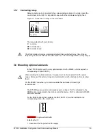
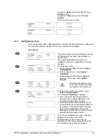
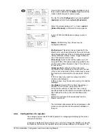
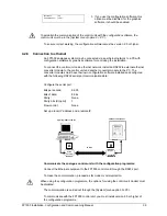
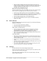
Resistor
150 Ohm
Resistor
150 Ohm /
¼ W
Maximum 1.2 Km
MASTER
SLAVE
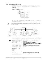
4.2.3 Configuration of the network
The FP1500 allows the interconnection of up to 10 control units and/or repeaters on a
network. The connection of control units is made through the RS485 serial port on the
main board.
Figure 15. Connection for RS485
The cable must be connected on the A and B terminals of each of the control units on the
network.
(See section 3.5.1)
To avoid communication problems, you must install a 150-Ohm / ¼ W resistor on the first
and last control units.
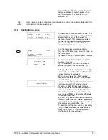
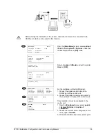
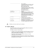
Once the control units are connected with their system installed, they must be configured
to form part of the network. Proceed as follows:
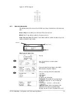
[MAIN MENU]
[# Exit]
1. Configure
4. Connect
7. See
2. Test.
5. Disconnect
3. Time
6. Print
You must define a unique address for each of the
control units.
From the
[Main Menu]
access
option 1
[Configuration]
and, in this option,
option 4 [System
Options]
.
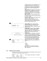
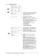
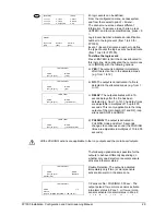
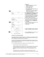
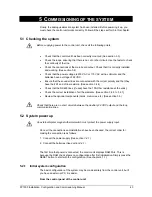
[CONFIGURE]
[# Exit]
1. System
4. System Op.
7.
Events
2. See Config. 5. Check Prog.
8. Day Mode
3. Time/Date 6. Power Supply 9. Codes
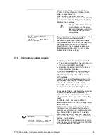
An information screen appears, move downwards
pressing
<Enter>
and a second information screen
appears.
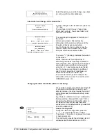
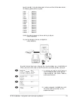
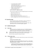
[SYSTEM OPTIONS]
[#Exit]
1. General
2. Messages
3. Modem
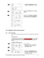
[SYSTEM OPTIONS]
[#Exit]
4. Network Address
Allocate a different number to each control unit in
[Network Address].
1