


FP1500 Installation, Configuration and Commissioning Manual
31
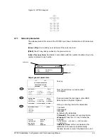
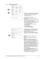
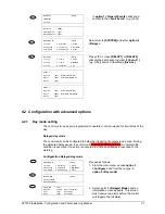
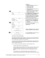
[EVENTS]
[#
Exit]
1. General
2. Logical
In
option 1 <General Events>
allocate a
number to the
<Fault Event>
(e.g. [004]).
Fault Event
:
[004]
Pre-Alarm Event
: [000]
Recognised Event : [000]
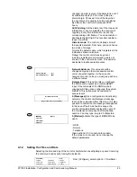
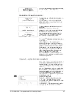
[CONFIGURE]
[#
Exit]
1. System
4. System Op.
7. Events
2. See Config.
5. Check Prog.
8. Day Mode
3. Time/Date
6. Power Supply
9. Codes
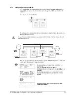
Now return to
[SYSTEM]
and enter
option 8
<Relays>.
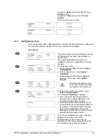
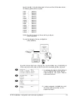
[SYSTEM]
[#
Exit]
1. Loop 1
4. Loop 4
7. Sirens
2. Loop 2
5. Loop 5
8. Relays
3. Loop 3
6. Peripherals
9. PC
Press
< 9 >
screen
[RELAY1]
or
[RELAY2]
allocate the same event number to
[Event-1]
(e.g. [004])
and set Initial Mode
[Inverse]
RELAY 1:
Logic line:
[001]
With Evacuation: NO]
Event-1:
[000]
Initial Mode: [NORMAL]
Event-2: [000]
RELAY 1:
Logic line:
[001]
With Evacuation: [NO]
Event-1:
[004]
Initial Mode: [INVERSE]
Event-2: [000]
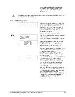
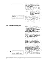
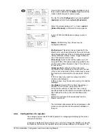
4.2 Configuration with advanced options
4.2.1 Day mode setting
The control unit can be pre-programmed to operate in certain ways at certain times of the
day:
Delayed day mode
The control unit can be configured to delay the triggering of outputs in any zone. During
the allocated delay period, the control unit receives an alarm warning. A complete fire
condition is executed if no action is executed in a time specified as a response to the
warning.
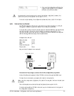
Configuration Delayed day mode
[CONFIGURE]
[#
Exit]
1. System
4. System Op.
7. Events
2. See Config.
5. Check Prog.
8. Day Mode
3. Time/Date
6. Power Supply
9. Codes
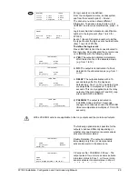
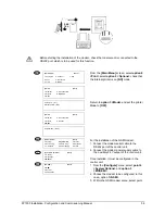
Proceed as follows:
1. From the main menu, access
option 1
<Configure>
and from there, type in
option 8 <Day mode>
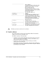
[DAY MODE]
[# Exit]
1. Delayed Mode
2. Sensitivity Mode
Allow Mode
: [NO]
Start Time
: [00:00]
End Time: [00:00]
Alert 1
: [010]
Secs Delay
Alert 2
: [030]
Secs Dela
y
2. Select: point
1 <Delayed Mode>
and an
information screen appears. This screen
must receive two alerts before the control
unit triggers the full alarm.
1
1
1
8
8
1