


FP1500 Installation, Configuration and Commissioning Manual
38
baud, 8 data bits, 1 stop bit without parity. In the case of the US Robotics modem,
the following parameters are required:
ATE0 + (ENTER)
ATQ0 + (ENTER)
ATV1 + (ENTER)
ATX3 + (ENTER)
AT&B1 + (ENTER)
AT&D0 + (ENTER)
AT&H0 + (ENTER)
AT&I0 + (ENTER)
AT&K0 + (ENTER)
AT&N6 + (ENTER)
AT&R1 + (ENTER)
AT&S0 + (ENTER)
AT&U6 + (ENTER)
So that the modem answers on the second ring, configure:
ATS0=2
(ENTER)
To save the changes of the new configuration:
AT&W
(ENTER)
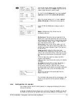
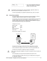
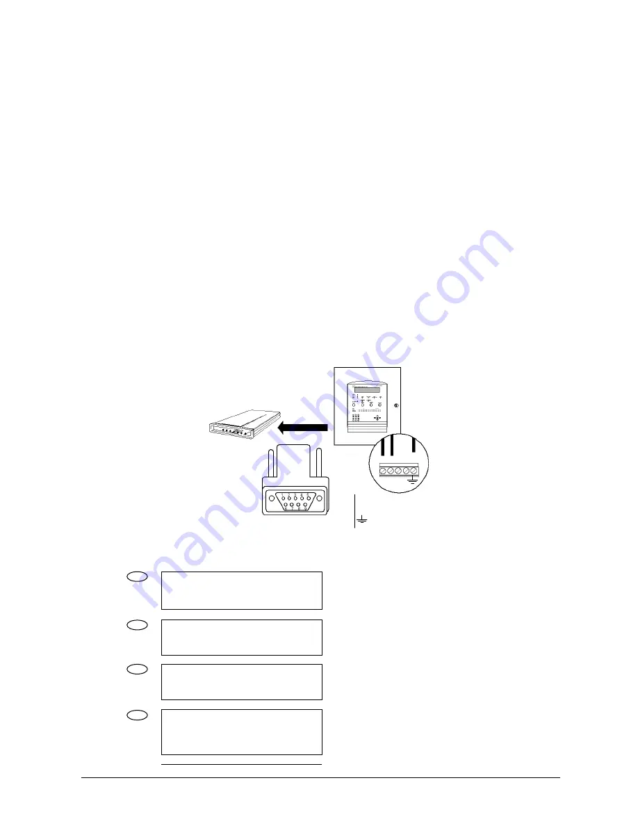
Once both modems have been configured, they may be installed, one on the RS232 port
of the control unit and the other on the PC that is to communicate with the control unit.
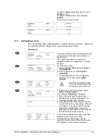
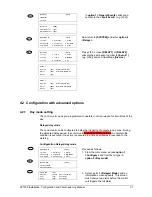
[CONFIGURE]
[# Exit]
1. System
4. System Op.
7.
Events
2. See Config. 5. Check Prog.
8. Day Mode
3. Time/Date 6. Power Supply 9. Codes
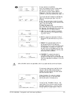
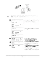
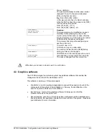
1. To configure the modem on the control unit,
from the configure menu, select option 4
<System Options>, then, point 3 <Modem>
and choose <Normal>.
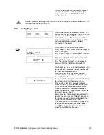
[SYSTEM OPTIONS]
[# Exit]
1. General
2. Messages
3. Modem
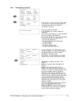
[MODEM]
[#
Exit]
1. GSM
2. Normal
3. Telephone
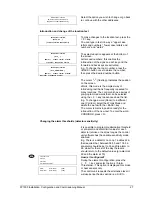
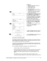
[NORMAL]
[#
Exit]
1. Options
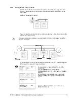
2. A submenu appears to establish the port of
the modem and asks whether or not to
activate the modem.
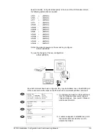
TXA RXB A B
RS1
TXA
RXB
2
3
5
4
2
1
3