– 30 –
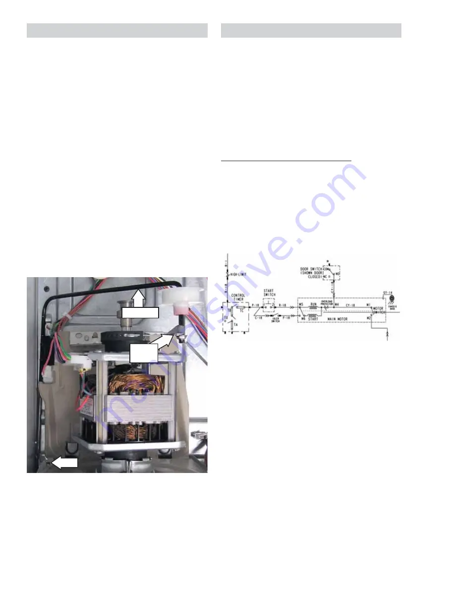
The idler assembly maintains proper tension
on the belt to minimize belt slippage. The idler
assembly consists of an idler pulley that rotates
on an idler arm. The pulley is retained on the
arm using a cap nut. The idler arm is positioned
on the dryer chassis and inserted in a slot in the
motor base plate. The assembly is located to the
left of the motor.
Idler Assembly Removal
1. Remove the drum. (See
Drum
in this section
of this service guide.)
WARNING
: The idler arm is under high tension.
To prevent injury, do not let the idler arm snap
back.
2. Release tension on the idler assembly by
unlocking the idler arm from the top right
corner of the motor bracket.
3. Remove the idler arm from the slot in the
motor base plate.
4. Remove the idler assembly from the dryer.
Slot
Idler Arm
Motor
Bracket
The drive motor is a single-speed, dual-shaft,
1/4-hp, 1725-rpm motor with an automatic reset
overload protector. The overload protector is
an internal component of the motor and cannot
be replaced separately. The motor contains a
centrifugal switch that serves three purposes:
It disengages the motor start winding (M6),
engages the motor run winding (M5), and closes
the circuit contacts (M1 to M2) for the heat
source.
'LDJQRVLQJWKH'U\HU'ULYH0RWRU
Motor Resistance Values
:
6WDUW:LQGLQJ
: 2.98 - 3.30 ohms
5XQ:LQGLQJ
: 3.19 - 3.53 ohms
To read the run winding resistance, or to see if
the motor overload protector is open, check from
terminal 2 on the start switch to the NO terminal
on the door switch. The start winding will need to
be read at the motor terminals M6 to M4.
(Continued Next Page)
Idler Assembly
Dryer Drive Motor and Blower Assembly
Содержание GUD24ESSMWW
Страница 16: ... 16 LUÀRZ ...
Страница 75: ... 75 Fault Code Binary Display ...
Страница 77: ... 77 LULQJ LDJUDPV To Washer Electric Dryer ...
Страница 78: ... 78 OHFWULF U HU RQJ 9HQW ORZHU 0RWRU LUFXLW ...
Страница 79: ... 79 To Washer Gas Dryer ...
Страница 80: ... 80 Power Supply To Washer Personality Jumper Plugs Washer ...


