GE Evolution Series E9000 Скачать руководство пользователя страница 26

Evolution Series E9000 User Manual

Chapter 5 – Maintenance

25

Equipment Maintenance


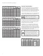
De-energize all equipment before performing any

maintenance operation. There may be voltage present 

within the equipment from remote sources, even 

though all main- and branch-circuit disconnects have  

been opened at the equipment. Failure to observe 

this precaution can result in serious injury or death.

The customer should prepare a maintenance program 

consisting of a schedule and checklist matrix listing items 

to be periodically examined on the installed equipment. 

The frequency and extent of the maintenance activities 

will vary depending on such factors as equipment usage 

and environmental conditions. In any maintenance  

program the following actions should be included:

1.   Remove accumulated dust and dirt with a soft 

cloth, brush or vacuum cleaner.

2.   Wipe clean all main bus insulators and vertical bus 

barriers.

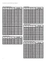
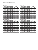
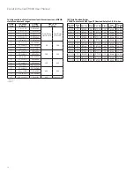
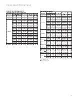
3.   Inspect main and vertical bus joints and main bus 

supports and tighten, if necessary. Refer to Table 1 

for torque specifications.

4.   Inspect all wiring from units for deterioration of 

insulation.

5.   Remove draw-out units and check stabs and all  

unit wiring. Remove accumulated dust from  

horizontal shelves and the areas around stabs.

6.   Check all starter contacts. They need only be 

replaced when nearly all the silver tip is gone and 

the contact tip support is exposed. Do not file the 

contacts. Filing or otherwise dressing the contacts 

only results in lost tip material and reduces starter 

life. See GE publication GET-6915A for questionable 

contact appearance.

7.   Check all unit wiring for deterioration of insulation 

and tighten all connections.

8.   Visually check meters and instruments. Check critical 

instrument calibrations.

9.  Check all unit door interlocks for proper operation.

10. Check all indicating lights and replace, as required.

11.  If fuse replacement is necessary, always install the 

same type and rating as the fuses furnished with the 

motor control center. Fuse designs may be mechani-

cally equivalent but not electrically equivalent. They 

may not have the same short-circuit withstand and 

current-limiting ability.

Inlet Filter Maintenance

Filter inspection and cleaning must be carried out every 

six months or more frequently as per your established 

maintenance plan. The frequency of filter maintenance 

or replacements should be determined individually, 

depending on dust accumulation and operating period.

Note: A soiled filter mat will cause the temperature to 

rise inside the enclosure. The filter mat can be regener-

ated by washing or blowing out.

Arc Resistant Maintenance

If a unit is removed from an Arc Resistant section for 

maintenance, a solid blank door should be used to  

cover the opening in order to maintain arc resistance.

Control Power

The option to have control power or test power during 

service is a functionality that has been provided with 

the Arc Resistant introduction of the LV MCC. This is a  

necessary requirement in order to check functions during 

service such as pilot lights and devices. This is intended 

to standardize the offerings when a customer orders 

common control power on the MCC. The two options we 

provide allow for 1) customer supplied 120VAC power 

or 2) self-contained control power within the MCC. 


The key switch is utilized to operate the control power  

when the stabs are disengaged. The key switch is turned  

“On” allowing the secondary control power to be utilized.  

The key switch should be “Off” during normal operation 

of the MCC.

Control Power Fusing

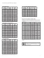
Control fuses are front accessible except in the 6-inch 

compact starter. Remove 6-inch FVNR starter for  

maintenance. Fuses are located on the side, as shown 

in Figure 40.

Figure 40. Fuse location

Содержание Evolution Series E9000

Страница 1: ...EvolutionSeries E9000 Motor Control Centers User Manual DEH 40472 Rev 08 GE Energy Connections...

Страница 2: ...s 16 Removal of Draw out Motor Control Center Units 18 Operating Handles Door Interlocks and Padlocking Provisions 18 Operating Handle 19 Pilot Bracket and Door 20 NEMA 3R Outdoor Enclosure Installati...

Страница 3: ...on information available at the time of its publication While efforts have been made to ensure accuracy the information contained herein does not cover all details or variations in hardware and softw...

Страница 4: ...ng splits Each shipping split is provided with continuous floor sills and a lifting angle Floor sills and lifting angles are field removable Each shipping split includes a continuous non removable mai...

Страница 5: ...rrier For Arc Resistant design uses this same Lexan barrier with additional Metallic dead front barrier The vertical bus either 300A or 600 850 A is connected with two bolts per phase to the main bus...

Страница 6: ...ous bolt sizes and joint types Bolt Size Copper Joints Aluminum Joints lb ft N m lb ft N m 5 16 18 5 9 7 12 6 5 9 9 12 3 8 16 12 16 16 22 10 15 14 20 1 2 13 30 39 41 53 25 35 34 47 5 8 11 65 80 88 108...

Страница 7: ...than the lifting angle or floor sills Use two or more chains or cables to distribute the weight evenly Pinch bars pipe rollers or slings are useful implements for handling equipment but be careful to...

Страница 8: ...urnished by the GE as well as all applicable contract drawings for the particular installation Pay particular attention to the location of units in the motor control center and their relations to exis...

Страница 9: ...Evolution Series E9000 User Manual 8 Indoor Enclosures Elevation and Mounting 30 Deep Sections 600A to 1200A Main Bus Top Conduit Entry 30 Deep Section...

Страница 10: ...t cable entry Note Bottom rear entrance should only be used with full rear accessibility Figure 6A Bottom conduit entrance details for standard 13 inch deep section low bus position Figure 6B Bottom c...

Страница 11: ...of the 13 inch deep section Surface under motor control center base must be of non combustible material unless bottom covers are installed in each vertical section The overall height of the equipment...

Страница 12: ...the section splits For additional gasket material orderpart number245A1888P5 Gaskets Figure 10A Type 12 and Arc Resistant gasket material between section splits NEC Work Space NEC Work Space is defin...

Страница 13: ...e tops of the sections through front or rear flaps as required For Arc Resistant sections with plenum the conduit can be assembled on top of the plenum GE offers an additional pull boxforhigherconduit...

Страница 14: ...e in Chapter 5 Exhaust Fan InstallationforULType 12 Enclosure and Arc Resistant Vented Fan Shields Filter Assembly UL Type 12 Fan Assembly Arc Resistant VFD Fan Shield Figure 16B Exhaust fan for UL Ty...

Страница 15: ...the cable insulation on any sharp edges such as steel work or screws Where access to the rear of the section is available cables can be brought into the space behind the vertical bus and brought forw...

Страница 16: ...ug is provided in each draw out combination starterunitforterminating a motor frame grounding wire For larger starters the lug is mounted on the horizontal ground bus 5 Use cord or plastic ties to sec...

Страница 17: ...cks are mounted on a metal rail located at the bottom of the unit as shown in Figure 22 The terminal block easily slides into position from either side of the mounting rail Figure 22 Mounting the term...

Страница 18: ...sure that all screw terminals are tight all foreign material and packing are removed and the insulating barriers are secure 7 The unit disconnect must be in the OFF position before the unit can be ins...

Страница 19: ...nadvertent contact Failure to observe this precaution can result in serious injury or death 5 Turn the latches at the top and bottom of the unit a quarter turn counterclockwise to release the unit The...

Страница 20: ...Size 5 FVNR 125 36 CAUTION should be used when removing or installing units considerthe weight intable above Two persons may be required orthe assistance of a lifting devices See page 21 for suggested...

Страница 21: ...er Note that the left module right rear cover has a flange that will be underneath the removed covered with it is replaced This provides an overlapping connection in the rear of the two spliced module...

Страница 22: ...Evolution Series E9000 User Manual 21...

Страница 23: ...at operating handles move freely to the TRIP indicating position With the door closed and latched reset each tripped circuit breaker by pushing the operating handle down beyond the OFF position The op...

Страница 24: ...nected during startup 8 Adjust instantaneous settings on magnetic onlycircuit breakers and or fuse sizes and overload heater selectionsto achieve propermotorand branch circuit protection See NEC Artic...

Страница 25: ...hown Figure 38 Adjust the pilot device bracket and extension bubble lip so it enters in between the keeper bracket and inside of the door Figure 39 Close the door completely and turn the 1 4 turn latc...

Страница 26: ...or interlocks for proper operation 10 Check all indicating lights and replace as required 11 If fuse replacement is necessary always install the same type and rating as the fuses furnished with the mo...

Страница 27: ...ables not required for accessories only 4 Remove the toggle holding plate toggle needs to be in the ON position UP 5 Remove the top four screws in top plate holding the breaker assembly not required f...

Страница 28: ...peed GEH 4806 NEMA Size 3 FVR 2 Speed GEH 4807 NEMA Size 4 FVR 2 Speed GEH 4839 NEMA Size 5 FVR 2 Speed GET 6915A Tech Info Contact Appearance Arc Flash Mitigation Units DEI 007 Remote Racking System...

Страница 29: ...keted 1 HG heavy gasketed 2 3R or 12 6 Power supply characteristics Voltage Number of phases Frequency in Hz 7 Control power voltage and frequency in Hz 8 Nameplate designation and title 9 Motor chara...

Страница 30: ...70 C379A 22 6 23 9 C273B 3 71 4 06 C419A 24 0 26 3 C303B 4 07 4 47 C466A 26 4 27 0 C330B 4 48 4 95 C526A Size 2 Standard and Ambient Comp Motor Full Load Amps 3 Ph 3 Heater Heater Number CR123 Motor...

Страница 31: ...f heater full load current multiplied by 1 25 Circuit breaker tripping may be an indication that a fault current has been interrupted To provide continued protection against fire or shock hazard exami...

Страница 32: ...1 C125B 15 3 6 11 2 12 1 C137B 15 3 7 11 2 12 1 C137B 30 LO 2 12 2 13 0 C151B 15 4 8 12 2 13 0 C151B 30 LO 2 13 1 15 5 C163B 30 1 3 15 6 16 8 C180B 30 1 4 16 9 18 0 C198B 30 2 5 18 1 19 7 C214B 30 2 5...

Страница 33: ...9 130 F161C 150 2 6 Size 5 Standard and Ambient Comp Motor Full Load Amps 3 Ph 3 Heater Heater Number CR123 TEC TECL Rating Mag Break Trip Setting Rec Max 106 115 C592A 550 1670 2 6 116 125 C630A 550...

Страница 34: ...8 81 9 27 C104B 15 3 5 9 28 9 99 C113B 20 2 4 10 0 11 1 C125B 20 2 5 11 2 12 1 C137B 20 3 5 12 2 13 0 C151B 20 3 5 13 1 15 5 C163B 20 4 6 15 6 16 8 C180B 25 3 5 16 9 18 0 C198B 25 3 6 18 1 19 7 C214B...

Страница 35: ...4C 150 3 5 93 5 105 0 F118C 150 3 5 106 0 114 0 F133C 150 3 5 115 0 128 0 F149C 150 4 6 129 0 130 0 F161C 150 4 6 Size 4 Standard Motor Full Load Amps 3 Ph 3 Heater Heater Number CR123 SE Rating Plug...

Страница 36: ...with a service factor of 1 0 multiply the motor full load current by 0 9 and use this value to select heaters Overload relay tripping current in 40 C ambient is the minimum value of full load current...

Страница 37: ...20 1 21 5 C228B 601 21 6 22 5 C250B 601 22 6 23 9 C273B 601 24 0 26 3 C303B 601 26 4 27 0 C330B 601 Size 2 Standard and Ambient Comp Motor Full Load Amps 3 Ph 3 Heater Heater Number CR123 Maximum Fuse...

Страница 38: ...70 6 F848B 2501 70 7 76 3 F914B 2751 76 4 88 7 F104C 3001 88 8 93 4 F114C 3501 93 5 105 F118C 3501 106 114 F133C 4001 115 128 F149C 4001 129 131 F161C 4001 132 135 F174C 4001 Size 5 300 15CT Standard...

Страница 39: ...4 78 5 06 C630A ElectronicOverloadforCircuitBreakerandFused Controllers The tripping current is 120 of the dial setting For continuous rated motors with a service factor of 1 15 to 1 25 set the dial...

Страница 40: ...4 0 CR324GXN 400 600 51 65 to 129 9 CR324GXP 51 130 to 270 CR324GXQ 62 130 to 259 9 CR324HXS 600 Class L 1200 1 300 15 CT s 2 800 5 CT s IECStyleOverloadRelays C2000ContactorCLNCJTypeRTOverloadRelayfo...

Страница 41: ...r Cat No FLA Range Lug Wire Size Torque in lbs Class 10 Class 20 LAR08AJ RTN2B NA 15 1 19 10 3 AWG 50 LAR10AJ RTN2C NA 19 1 25 10 3 AWG 50 RTN2D RT22D 25 1 32 10 3 AWG 50 RTN2E RT22E 32 1 43 10 3 AWG...

Страница 42: ...Evolution Series E9000 User Manual 41 Notes...

Страница 43: ...42 Evolution Series E9000 User Manual Notes...

Страница 44: ...eneral Electric Company 2017 General Electric Company Information provided is subject to change without notice All values are design or typical values when measured under laboratory conditions DEH 404...

Отзывы: