GEI-50299 Power Circuit Breakers Types AK-2 -15
and
AK-2/3-25
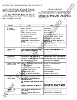
Should the mechanism continue to function
improperly after the proper latch engagement
has been set and the corrective measures listed
in the "Trouble Shooting" chart carried out, it is
generally recommended that no attempt be made
to repair the mechanism interior but that a re
placement mechanism assembly be obtained from
the factory.
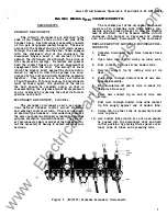
REPLACEMENT
1.
If the breaker is electrically operated, remove
the front escutcheon by taking four screws
from flange.
If
the breaker is a drawout type,
two small round head screws must also be
removed from the bottom edge of the escutch
eon. (For removal of front escutcheon from
manually operated breakers, see procedure
described below.)
2. Remove arc quenchers (See "Arc Quencher").
3. Disconnect the two insulated connecting links
between the mechanism and the contacts as in
step 2 of the procedure for "Separation of
Front and Back Frames".
4. Remove the two elastic stop nuts, which fasten
the upper extensions of mechanism frame to
studs connecting with rear frame.
5.
Remove four screws which fasten the bottom
of the mechanism frame to the horizontal
cross member of the front frame.
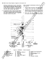
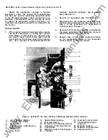
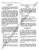
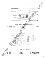
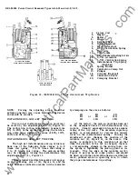
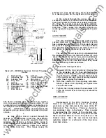
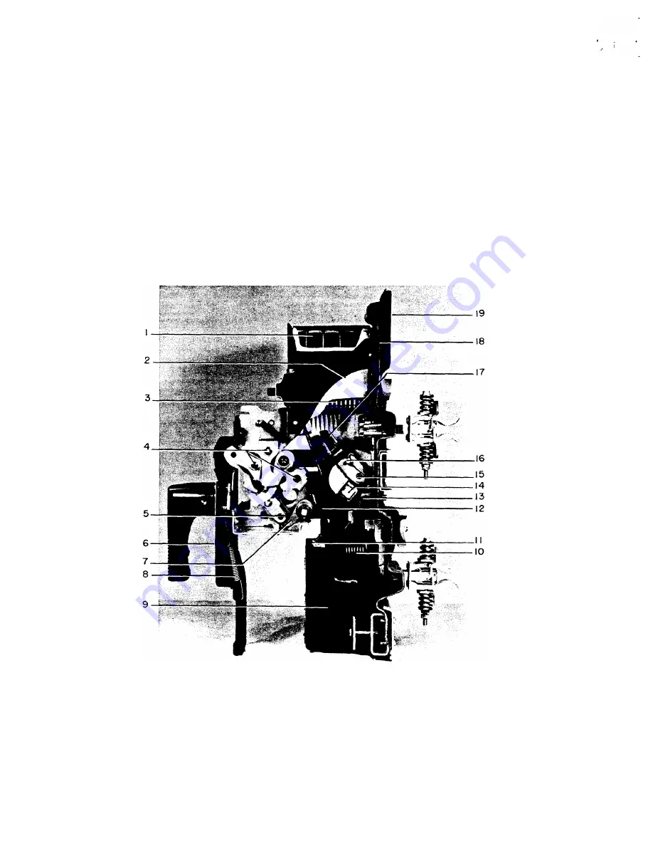
Figure 6. (8024516) Cut Away Model of Manually Operated AK-2 Breaker
1.
2.
3.
4.
5.
6.
7.
14
Arc Quencher Muffler
Ceramic Side Plates
Steel Plates
Fixed Centers in Mechanism
Latch Roller
Escutcheon
Trip Latch
8.
9.
10.
11.
12 .
13.
14.
Handle Return Spring
Overload Device
Series Coil of Overload Device
Trip Arm of Overload Device
Trip Paddle
Movable Contact Pivot Support
Crossbar
15. Movable Contact Pivot
16. Contact Wipe Adjust-
ment Pin
17. Movable Contact
18. Moulded Compound Bar
19. Steel Back Plate
•
www
. ElectricalPartManuals
. com


