- - - - -,
I
I
_ _ _ _ J
C u s T e> ME R S
T � ll N 5 FORMH<
Z. 3o v'. iO o � s E c .
M I N I MUM S IZ E
I D O VA
cs
A - 2 50V D.C RI: L A'r'
C1 ,C4 ,C.< ,Cc.,C7 - .IDA.<f t iO'lo
c;,oo W VD C .
C t
· 5Soxf 350
WVDC
C 3 - l o o o
"f
z oo w v D C
Do,D4. D5 D• , D7
•
I N S
60
-
;o o o m "-
�
3o'c
Rl · t5 A
h.J
! S ')'.
R � - t 5o o .n
SW t s %
R 3 · 75 .n.. 5 W
t
5 '7o
R4, Rs, Ro, R1 -
10
.n.
Y2
w
R e - <.750 -"-
2. o w
t s r.
R
H
-
0
-
25,
ooo
_n_ 25 Vv'
R , - 5oo ..n.
3 W : .5 '7•
breaker having the longer setting and higher pick
up, provided the fault is on the part of the line
protected by the breaker having the lower setting.
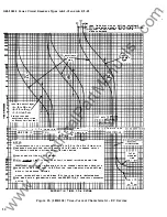
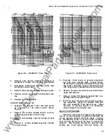
For the exact characteristics and setting of
each breaker in a selective system, reference
should be made to a coordination chart for the
particular system .
(Figures 23, 2 4 , and 25)
STATIC TIME DELAY
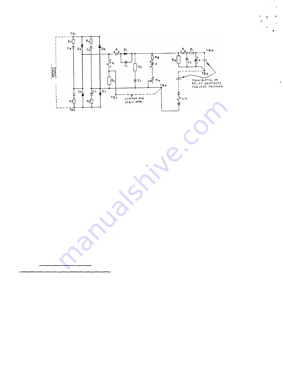
UNDERVOLTAGE TRIPPING DEVICE
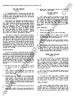
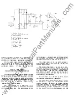
The Static Time Delay Undervoltage Tripping
Device consists of an undervoltage device mounted
on the breaker, a static time delay box m::mnted
separately from the breaker and a control power
transformer which is also mounted separately from
the breaker when the reference voltage is ;Jther
than D C ., 2 08V AC or 230V AC . Refer to wiring
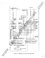
diagram 0102 C3 698 (Figure 2 6) .
The voltage 208V A C o r 230V A C , to be
monitored is connected to terminals #1 and #2
of the time delay box. The undervoltage device
32
T(' t .: C o N N E c T tr. o
!:' { c • • : T O M E R . t •
I N S T I S N OT
RE'Q'D.
Ju tv�PE P
UV
To T B S
o n the breaker i s always connected through either
its secondary disconnects or terminal board, tp
terminals #4 and #5 of the time delay box.
The undervoltage device is set to pickup at
approximately 80% of bus voltage and drop out
between 30% and 60%.
The undervoltage device coil circuit is con
tinuously rated and will remain picked up as long
as the voltage remains above the predetermined
drop out voltage. The time delay is field adjust
able between 1 and 5 seconds, it is factory set at
the minimum setting, and once the time delay is
established, it is consistent.
No more than one undervoltage device should
be connected to a static time delay box.
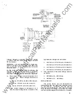
The Static Time Delay Undervoltage can also
be furnished in conjunction with the termotector
control package, as shown on wiring diagram
0 1 02 C3 699 (Figure 2 7 ) . Overheating of the motor
windings causes the termotector, imbedded in the
motor windings, to open and allow the
"Z"
relay
of the control box to instantaneously trip the
www
. ElectricalPartManuals
. com

