


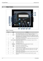

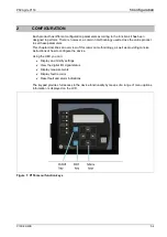
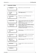

4 Front Panel
P50 Agile P153
4-6
P153/EN M/B
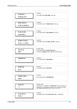
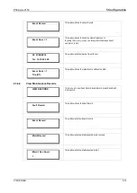
SL no
Label
Function
LED 1
ON
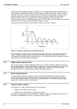
Green LED indicates that the IED is in correct working order, and should be ON at all times. It
turns red if the unit’s self-tests show there is an error in the hardware or software.
LED 2
START
Amber LED flashes when the IED registers an alarm. This may be triggered by a fault, event or
maintenance record. The LED flashes until the alarms have been accepted (read) by pressing
VIEW RECORD function key, then changes to constantly ON. When the alarms are cleared, the
LED switches OFF after pressing CLEAR key.
LED 3
TRIP
Red LED switches ON when the IED issues a trip signal. When the faults are cleared, the LED
switches OFF after pressing CLEAR key.
LED 4
OUT OF SERVICE Amber LED flashes when the IED's protection is unavailable (eg. Setting Error, ADC Error
detected by unit’s self-test etc)
LED 5,6
-
Programmable dual colour LED
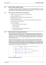
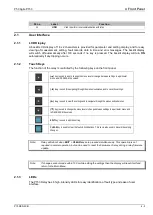
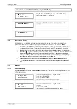
2.1.4
RS 485 Port
RS485 port is provided at the rear of relay (near to terminal block) for permanent SCADA connectivity.
The separate 3 pin connector is used to avoid accidental connection of power wiring to communication
input. The RS485 port can be used to download Settings, Fault data, Live Events and Disturbance
Records.
2.1.5
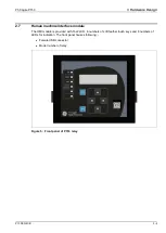
USB Port
The USB port is situated on the front panel in the bottom right hand corner, and can be accessed by
opening the flap on the front of the relay. This port is used to communicate with a locally connected
PC.
It has three main purposes:
•
Transferring settings information to/from the PC from/to the device.
•
Downloading firmware updates.
•
Downloading relay data for analysis.
The port is intended for temporary connection during testing, installation and commissioning. It is not
intended to be used for permanent SCADA communications.
You can connect the unit to a PC with a USB cable up to 15 m in length.
The USB port includes a USB full-speed function controller, USB transceiver, oscillator, EEPROM, and
synchronous serial data bus (UART). No other external USB components are required.
For configuration/setting, appropriate ‘Config port’ has to be selected from the
SYSTEM DATA
menu.
Содержание Agile P50 Series
Страница 3: ...P50 Agile P153 1 Introduction P153 EN M B 1 1 INTRODUCTION CHAPTER 1...
Страница 4: ...1 Introduction P50 Agile P153 1 2 P153 EN M B...
Страница 10: ...1 Introduction P50 Agile P153 1 8 P153 EN M B...
Страница 11: ...P50 Agile P153 2 Safety Information P153 EN M A 2 1 SAFETY INFORMATION CHAPTER 2...
Страница 22: ...Chapter 2 Safety Information P50 Agile P153 2 12 P153 EN M A...
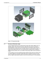
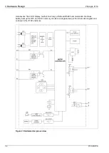
Страница 23: ...P50 Agile P153 3 Hardware Design P153 EN M B 3 1 HARDWARE DESIGN CHAPTER 3...
Страница 24: ...3 Hardware Design P50 Agile P153 3 2 P153 EN M B...
Страница 32: ...3 Hardware Design P50 Agile P153 3 10 P153 EN M B...
Страница 33: ...P50 Agile P153 4 Front Panel P153 EN M B 4 1 FRONT PANEL CHAPTER 4...
Страница 34: ...4 Front Panel P50 Agile P153 4 2 P153 EN M B...
Страница 39: ...P50 Agile P153 5 Configuration P153 EN M B 5 1 CONFIGURATION CHAPTER 5...
Страница 40: ...P50 Agile P153 5 Configuration P153 EN M B 5 2...
Страница 150: ...P50 Agile P153 5 Configuration P153 EN M B 5 112...
Страница 151: ...P50 Agile P153 6 Protection Functions P153 EN M B 6 1 PROTECTION FUNCTIONS CHAPTER 6...
Страница 152: ...6 Protection Functions P50 Agile P153 6 2 P153 EN M B...
Страница 167: ...P50 Agile P153 7 Protection Parameter Settings P153 EN M B 7 1 PROTECTION PARAMETER SETTINGS CHAPTER 7...
Страница 168: ...7 Protection Parameter Settings P50 Agile P153 7 2 P153 EN M B...
Страница 189: ...P50 Agile P153 8 Monitoring Control P153 EN M B 8 1 MONITORING CONTROL CHAPTER 8...
Страница 190: ...8 Monitoring Control P50 Agile P153 8 2 P153 EN M B...
Страница 207: ...P50 Agile P153 9 SCADA Communications P153 EN M B 9 1 SCADA COMMUNICATIONS CHAPTER 9...
Страница 208: ...12 SCADA Communications P50 Agile P153 9 2 P153 EN M B...
Страница 220: ...12 SCADA Communications P50 Agile P153 9 14 P153 EN M B...
Страница 221: ...P50 Agile P153 10 Installation P153 EN M B 10 1 INSTALLATION CHAPTER 10...
Страница 222: ...10 Installation P50 Agile P153 10 2 P153 EN M B...
Страница 232: ...10 Installation P50 Agile P153 10 12 P153 EN M B 2 4 Case dimensions Figure 10 Case dimensions Note All dimensions in mm...
Страница 233: ...P50 Agile P153 13 Commissioning Instructions P153 EN M B 13 1 COMMISSIONING INSTRUCTIONS CHAPTER 11...
Страница 234: ...13 Commissioning Instructions P50 Agile P153 13 2 P153 EN M B...
Страница 241: ...P50 Agile P153 12 Maintenance and Troubleshooting P153 EN M B 12 1 MAINTENANCE AND TROUBLESHOOTING CHAPTER 12...
Страница 242: ...12 Maintenance and Troubleshooting P50 Agile P153 12 2 P153 EN M B...
Страница 250: ...12 Maintenance and Troubleshooting P50 Agile P153 12 10 P153 EN M B...
Страница 251: ...P50 Agile P153 13 Technical Specifications P153 EN M B 13 1 TECHNICAL SPECIFICATIONS CHAPTER 13...
Страница 252: ...13 Technical Specifications P50 Agile P153 13 2 P153 EN M B...
Страница 263: ...P50 Agile P153 14 Wiring Diagrams P153 EN M B 14 1 WIRING DIAGRAMS CHAPTER 14...
Страница 264: ...14 Wiring Diagrams P50 Agile P153 14 2 P153 EN M B...
Страница 266: ...14 Wiring Diagrams P50 Agile P153 14 4 P153 EN M B 2 WIRING DIAGRAM Figure 1 P153 wiring diagram...
Страница 267: ......