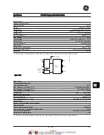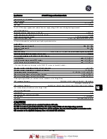
Control card, 10 V DC output
Terminal number
50
Output voltage
10.5 V
±
0.5 V
Max. load
25 mA
The 10 V DC supply is galvanically isolated from the supply voltage (PELV) and other high-voltage terminals.
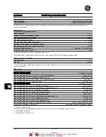
Control characteristics
Resolution of output frequency at 0–1000 Hz
±
0.003 Hz
System response time (terminals 18, 19, 27, 29, 32, 33)
≤
2 ms
Speed control range (open-loop)
1:100 of synchronous speed
Speed accuracy (open-loop)
30-4,000 rpm: Maximum error of
±
8 rpm
All control characteristics are based on a 4-pole asynchronous motor
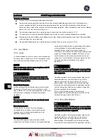
Surroundings
Enclosure, frame size 4X and 5X
IP00, IP21, IP54
Enclosure, frame size 6X
IP21, IP54
Vibration test
0.7 g
Relative humidity
5%–95% (IEC 721-3-3; Class 3K3 (non-condensing) during operation
Aggressive environment (IEC 60068-2-43) H
2
S test
class kD
Test method according to IEC 60068-2-43 H2S (10 days)
- with derating
max. 131° F [55
°
C]
1)
- with full output power, typical EFF2 motors
max. 122° F [50
°
C]
1)
- at full continuous drive output current
max. 113° F [45
°
C]
1)
1)
For more information on derating see the AF-600 FP, section on Special Conditions.
Minimum ambient temperature during full-scale operation
32° F [0
°
C]
Minimum ambient temperature at reduced performance
14° F [-10
°
C]
Temperature during storage/transport
-13°–149°/158° F [-25°–+65°/70
°
C]
Maximum altitude above sea level without derating
3,300 ft [1,000 m]
Maximum altitude above sea level with derating
10,000 ft [3,000 m]
Derating for high altitude, see section on special conditions in the Design Guide
EMC standards, Emission
EN 61800-3, EN 61000-6-3/4, EN 55011, IEC 61800-3
EMC standards, Immunity
EN 61800-3, EN 61000-6-1/2,
EN 61000-4-2, EN 61000-4-3, EN 61000-4-4, EN 61000-4-5, EN 61000-4-6
See section on special conditions in the Design Guide!
Control card performance
Scan interval
5 ms
Control card, USB serial communication
USB standard
1.1 (Full speed)
USB plug
USB type B “device” plug
CAUTION
Connection to PC is carried out via a standard host/device USB cable.
The USB connection is galvanically isolated from the supply voltage (PELV) and other high-voltage terminals.
The USB connection is not galvanically isolated from ground protection. Use only isolated laptop/PC as connection to the
USB connector on the adjustable frequency drive or an isolated USB cable/drive.
Specifications
AF-600 FP Design and Installation Guide
DET-768A
12-15
12
12
Содержание AF-600 FP Series
Страница 1: ...AF 600 FPTM Fan Pump Drive Design and Installation Guide GE ...
Страница 17: ...Introduction AF 600 FP Design and Installation Guide 1 10 DET 768A 1 1 ...
Страница 39: ...Start Up and Functional Tes AF 600 FP Design and Installation Guide 3 6 DET 768A 3 3 ...
Страница 57: ...About Programming AF 600 FP Design and Installation Guide 5 14 DET 768A 5 5 ...
Страница 73: ...Application Set up Examples AF 600 FP Design and Installation Guide 6 16 DET 768A 6 6 ...
Страница 83: ...Installation Consideration AF 600 FP Design and Installation Guide 7 10 DET 768A 7 7 ...
Страница 87: ...Status Messages AF 600 FP Design and Installation Guide 8 4 DET 768A 8 8 ...
Страница 97: ...Warnings and Alarms AF 600 FP Design and Installation Guide 9 10 DET 768A 9 9 ...
Страница 101: ...Basic Troubleshooting AF 600 FP Design and Installation Guide 10 4 DET 768A 10 0 ...
Страница 103: ...Terminal and Applicable Wir AF 600 FP Design and Installation Guide 11 2 DET 768A 11 1 ...


