


CHAPTER 1: COMMUNICATIONS GUIDE
FIELDBUS INTERFACE
MM300 MOTOR MANAGEMENT SYSTEM – COMMUNICATIONS GUIDE
89
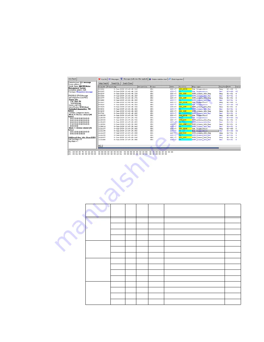
The following diagram shows an example of the extended diagnostic data sent to the
Profibus master by the MM300. The extended diagnostic data is only provided when one of
the states listed in the above extended diagnostic table has become true. In this example,
the extended diagnostic data has been sent because the "External Start A Alarm" is active.
Such a case would occur when the motor status is running, but no Start A control was
issued by the MM300. In this case, multiple alarms have occurred in the MM300, including
one that indicates that FLA is not set.
Figure 6: Profibus - extended diagnostic data
Profibus DPV1
The MM300 relay also supports DPV1 extensions. The device supports Class 1 and Class 2
acyclic reads and writes as well as DPV1 Diagnostics.
Profibus DPV1-Acyclic
read/write data
The motor status data can be read acyclically by retrieving the byte lengths indicated
below from the relevant Object, Slot, Index.
Table 14: DPV1 Acyclic read data
Category
Object Slot
Index Length
(in
Bytes)
Data Item
Format
Status-Motor
0
0
0
2
Motor Status
FC129
0
0
2
2
Extended Status
FC178
0
0
4
2
Thermal Cap Used
F1
0
0
6
4
Time to Overload Trip
F20
Start Blocks
0
0
10
2
Starts/Hour Block
F1
0
0
12
2
Time Between Starts Lockout
F1B
0
0
14
2
Restart Block Lockout
F1
Learned
0
0
16
2
Average Motor Load Learned
F3
0
0
18
2
Learned Acceleration Time
F2
0
0
20
4
Learned Starting Current
F10
0
0
24
2
Learned Starting Capacity
F1
Counters
0
0
26
2
Number of Motor Starts
F1
0
0
28
2
Number of UV Restarts
F1
0
0
30
4
Motor Running Hours
F9
0
0
34
2
Motor Stopped Hours
F1