25
232001260G(10)
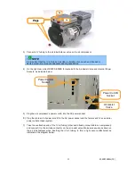
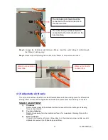
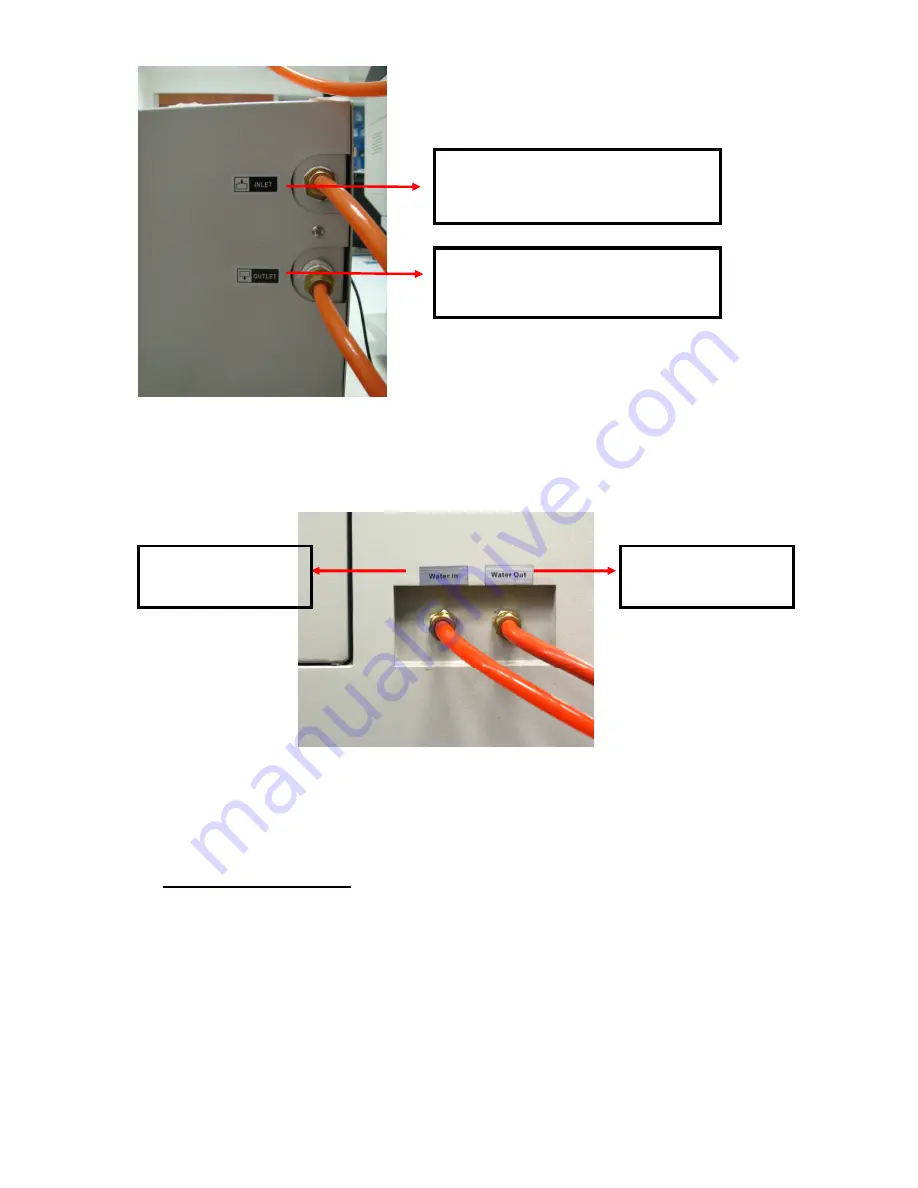
Step 2. Arrange the Outlet and Inlet tubing as follows. Insert the outlet tubing of chiller through
the “Water in” slot opening.
Step 3. Connect the outlet tubing from chiller to the “Water in” connector on machine.
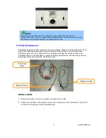
4.1.6 Adjustable Air Nozzle
The Air nozzle can be adjusted to create different distances to the working piece for different air
blowing effect to meet various application demands and prevent dust accumulating on the lens.
NOZZLE ADJUSTMENT:
1)
Clockwise
Nozzle moves closer to the material surface to have a direct and stronger air blowing
force on the material.
2)
Counter-clockwise
Nozzle moves away from the material surface to for a weaker air blowing force on the
material..
3)
Remove Nozzle
If you do not need a strong air blow direct on the material, screw nozzle counter-
clockwise to remove it and have an open air blow.
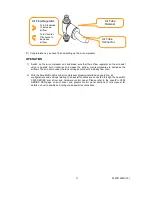
The outlet tubing of chiller should be
connected to the inlet connector on the
laser machine.
The inlet tubing of chiller should be
connected to the outlet connector on
the laser machine.
Water out connector
on laser tube
Water in connector on
laser tube
Содержание LaserPro X500 III-80Y
Страница 1: ...0 232001260G 10...
Страница 7: ...6 232001260G 10...
Страница 8: ...7 232001260G 10...
Страница 9: ...8 232001260G 10 CDRH Label This label indicates the class level of CDRH...
Страница 31: ...30 232001260G 10...
Страница 32: ...31 232001260G 10...
Страница 37: ...36 232001260G 10...
Страница 38: ...37 232001260G 10...
Страница 82: ...232001260G 10 81...
Страница 83: ...232001260G 10 82...
Страница 103: ...232001260G 10 102 Step 1 Produce the gray level background...
Страница 105: ...232001260G 10 104 Step 2 Produce three dimensional characters...

