


Installation
2
Dimple Grinder User’s Guide
2.0 Installation
The Dimple Grinder operates from the standard mains voltage with no other
external services or utilities necessary. However, for reproducible high-quality
results, the Dimple Grinder must sit on a flat, vibration-free surface in a rela-
tively clean environment.
The Counterweight is packed separately and should be attached by screwing it
into position on the Platform. After installation, the zero point of the Counter-
weight scale should be checked (see Section 5.2).
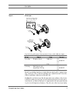
3.0 Description
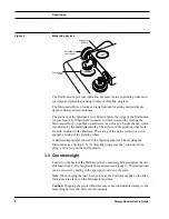
The base (body) of the Dimple Grinder (see Figure 1) holds the Control Panel,
the Micrometer Drive, the Magnetic Turntable with motor drive, the Raise/
Lower Cam, and the Transmission Illumination system. On top of this base sits
a pivoted Platform containing the Grinding Wheel assembly, the analog Dial
Indicator, and the Counterweight. The Platform, when in the vertical position, is
held in place by a magnetic latch (at the rear). With the Platform raised, a stereo
microscope can be mounted over the Magnetic Turntable for specimen viewing.
3.1 Control Panel
The Control Panel contains the following buttons and dials:
3.2 Measuring Devices
The Dimple Grinder incorporates two measuring devices:
•
A Dial Indicator with stylus and analog display (see Figure 8).
•
A Micrometer Drive connected to a digital display (see Figure 2).
Table
Depress to turn on/off motor for magnetic turntable rotation.
Arm
Depress to turn on/off motor for dimple wheel rotation.
Lamp
Depress to turn on/off transmission illumination.
Auto
Depress to turn on/off AutoTerminator.
Zero
Depress to zero Dimple Depth digital display.
Speed (dial)
Rotate to set dimpling wheel rotation speed.
Содержание 656
Страница 2: ...Part Number 656 82002...
Страница 6: ...iv Dimple Grinder User s Guide...
Страница 10: ...viii Dimple Grinder User s Guide...
Страница 42: ...Spares and Consumables 32 Dimple Grinder User s Guide...
Страница 44: ...I 2 Dimple Grinder User s Guide...
Страница 48: ......