background image

Adjusting the Range of the Depth or Width Scale

You can adjust the range of the depth scale traditional 
and Garmin ClearVü sonar views and the range of the 
width scale for the SideVü sonar view.
Allowing the device to adjust the range automatically 
keeps the bottom within the lower or outer third of the 
sonar screen, and can be useful for tracking a bottom that 
has minimal or moderate terrain changes.
Manually adjusting the range enables you to view a 
specified range, which can be useful for tracking a bottom 
that has large terrain changes, such as a drop-offs or 
cliffs. The bottom can appear on the screen as long as it 
appears within the range you have set.

1

From a sonar view, select 

Menu

 > 

Range

.

2

Select an option:
• To allow the chartplotter to adjust the range 

automatically, select 

Auto

.

• To increase or decrease the range manually, select 

Up

 or 

Down

.

TIP: 

From the sonar screen, you can select 

 or 

to manually adjust the range.

TIP: 

When viewing multiple sonar screens, you can 

select Select to choose the active screen.

Sonar Noise Rejection Settings

From a sonar view, select 

Menu

 > 

Sonar Setup

 > 

Noise 

Reject

.

Interference

: Adjusts the sensitivity to reduce the effects 

of interference from nearby sources of noise.
The lowest interference setting that achieves the 
desired improvement should be used to remove 
interference from the screen. Correcting installation 
issues that cause noise is the best way to eliminate 
interference.

Color Limit

: Hides part of the color palette to help 

eliminate fields of weak clutter.
By setting the color limit to the color of the undesired 
returns, you can eliminate the display of undesired 
returns on the screen.

Smoothing

: Removes noise that is not part of a normal 

sonar return, and adjusts the appearance of returns, 
such as the bottom.
When smoothing is set to high, more of the low-level 
noise remains than when using the interference 
control, but the noise is more subdued because of 
averaging. Smoothing can remove speckle from the 
bottom. Smoothing and interference work well together 
to eliminate low-level noise. You can adjust the 
interference and smoothing settings incrementally to 
remove undesirable noise from the display.

Surface Noise

: Hides surface noise to help reduce 

clutter. Wider beam widths (lower frequencies) can 
show more targets, but can generate more surface 
noise.

TVG

: Adjusts the time varying gain, which can reduce 

noise.

This control is best used for situations when you want 
to control and suppress clutter or noise near the water 
surface. It also allows for the display of targets near the 
surface that are otherwise hidden or masked by 
surface noise.

Sonar Appearance Settings

From a sonar view, select 

Menu

 > 

Sonar Setup

 > 

Appearance

.

Color Scheme

: Sets the color scheme.

Color Gain

: Adjusts the intensity of colors (

Adjusting the 

Color Intensity

, page 37

).

A-Scope

: Displays a vertical flasher along the right side 

of the screen that shows instantaneously the range to 
targets along a scale.

Depth Line

: Shows a quick-reference depth line.

Edge

: Highlights the strongest signal from the bottom to 

help define the hardness or softness of the signal.
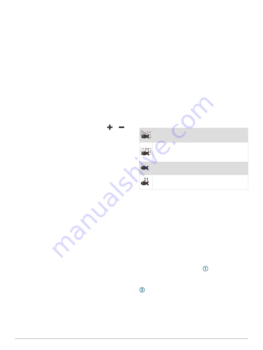
Fish Symbols

: Sets how the sonar interprets suspended 

targets.

Shows suspended targets as symbols and 
background sonar information.

Shows suspended targets as symbols with 
target depth information and background sonar 
information.

Shows suspended targets as symbols.

Shows suspended targets as symbols with 
target depth information.

Pic. Advance

: Allows the sonar picture to advance faster 

by drawing more than one column of data on the 
screen for each column of sounder data received. This 
is especially helpful when you are using the sounder in 
deep water, because the sonar signal takes longer to 
travel to the water bottom and back to the transducer.
The 1/1 setting draws one column of information on the 
screen per sounder return. The 2/1 setting draws two 
columns of information on the screen per sounder 
return, and so on for the 4/1 and 8/1 settings.

Echo Stretch

: Adjusts the size of the echoes on the 

screen to make it easier to see separate returns on the 
screen.
When targets are difficult to see 

, echo stretch 

makes the target returns more pronounced and easier 
to see on the screen. If the echo stretch value is too 
high, the targets blend together. If the value is too low 

, the targets are small and more difficult to see.

Sonar Fishfinder

39

Содержание Volvo Penta Glass Cockpit B12

Страница 1: ...Owners manual VOLVO PENTA Glass Cockpit ...

Страница 2: ...ries These trademarks may not be used without the express permission of Garmin Volvo Penta is a registered trademark of Volvo Trademark Holding AB Apple and Mac are trademarks of Apple Inc registered in the U S and other countries Android is a trademark of Google Inc The BLUETOOTH word mark and logos are owned by the Bluetooth SIG Inc and any use of such marks by Garmin is under license CZone is a...

Страница 3: ... Automatically Turning Off the System 7 ActiveCaptain App 7 ActiveCaptain Roles 7 Getting Started with the ActiveCaptain App 7 Enabling Smart Notifications 8 Receiving Notifications 8 Managing Notifications 8 Making Notifications Private 8 Updating Software with the ActiveCaptain App 8 Updating Charts with ActiveCaptain 9 Communication with Wireless Devices 9 Wi Fi Network 9 Setting Up the Wi Fi W...

Страница 4: ...Using the Garmin Quickdraw Contours Feature 20 Adding a Label to a Garmin Quickdraw Contours Map 20 Garmin Quickdraw Community 20 Connecting to the Garmin Quickdraw Community with ActiveCaptain 20 Downloading Garmin Quickdraw Community Maps Using ActiveCaptain 20 Sharing Your Garmin Quickdraw Contours Maps with the Garmin Quickdraw Community Using ActiveCaptain 20 Connecting to the Garmin Quickdra...

Страница 5: ... a Track to a Boundary 29 Editing a Boundary 29 Linking a Boundary to a SmartMode Layout 29 Setting a Boundary Alarm 29 Disabling all Boundary Alarms 29 Deleting a Boundary 29 Deleting All Saved Waypoints Tracks Routes and Boundaries 29 Sailing Features 29 Setting the Vessel Type for Sailing Features 29 Sail Racing 29 Starting Line Guidance 29 Setting the Starting Line 30 Using the Starting Line G...

Страница 6: ...oom Level 42 Adjusting the RealVü Sweep Speed 42 LiveVü Forward and FrontVü Sonar Menu 42 Setting the LiveVü and FrontVü Transducer Transmit Angle 42 Setting the FrontVü Depth Alarm 42 LiveVü and FrontVü Appearance Settings 43 LiveVü and FrontVü Layout Settings 43 RealVü Appearance Settings 43 LiveScope and Perspective Sonar Menu 43 LiveScope and Perspective Sonar Setup 44 LiveScope and Perspectiv...

Страница 7: ...aver 52 Enabling Shadow Drive 52 Autopilot Overlay Bar 53 Engaging the Autopilot 53 Adjusting the Heading with the Helm 53 Adjusting the Heading with the Chartplotter in Step Steering Mode 53 Steering Patterns 53 Following the U Turn Pattern 53 Setting Up and Following the Circles Pattern 53 Setting Up and Following the Zigzag Pattern 53 Following the Williamson Turn Pattern 53 Following an Orbit ...

Страница 8: ...sistant 60 Oil Level Information 60 Driveline Information 60 EVC Network Information 60 Easy Connect Information 60 inReach Messages 61 Connecting an inReach Device to the Chartplotter 61 Receiving inReach Messages 61 Sending an inReach Preset Message 61 Replying to an inReach Message 61 Digital Switching 61 Adding and Editing a Digital Switching Page 61 Dometic Optimus Features 61 Activating the ...

Страница 9: ...and Subscription Requirements 67 Weather Data Broadcasts 67 Weather Warnings and Weather Bulletins 67 Changing the Weather Chart 67 Viewing Precipitation Information 67 Storm Cell and Lightning Information 67 Hurricane Information 67 Forecast Information 67 Viewing a Marine Forecast or an Offshore Forecast 68 Viewing Forecast Information for Another Time Period 68 Weather Fronts and Pressure Cente...

Страница 10: ... label Regulatory and Compliance Information 76 Preferences Settings 76 Units Settings 76 Navigation Settings 76 Auto Guidance Path Configurations 76 Adjusting the Distance from Shore 77 Communications Settings 77 NMEA 0183 Settings 77 Configuring NMEA 0183 Output Sentences 78 Setting the Communication Format for Each NMEA 0183 Port 78 NMEA 2000 Settings 78 Naming Devices and Sensors on the Networ...

Страница 11: ...tplotter from the GRID Device 86 Rotating the GRID Remote Input Device 86 Cleaning the Screen 86 Viewing Images on a Memory card 86 Screenshots 86 Capturing Screenshots 86 Copying Screenshots to a Computer 86 Troubleshooting 86 My device will not acquire GPS signals 86 My device will not turn on or keeps turning off 86 My device is not creating waypoints in the correct location 86 Contacting Volvo...

Страница 12: ......

Страница 13: ... of our advice on boat operations and maintenance before you make your first trip Pay attention to the safety instructions in the manual We would also like to welcome you to our world wide network of distributors and repair shops which can help you with technical advice service and spare parts The Volvo Penta website at support garmin com presents up to date information about your product The supp...

Страница 14: ...are not guaranteed to be fully compatible in a combination page or SmartMode layout or when accessories such as a radar are connected Button Function Clears the on screen icons and re centers the screen on the boat Opens a full screen view of the item Creates a new waypoint Creates a route with turns to the destination Adds a turn to the route at the selected location Removes the last added turn f...

Страница 15: ... features and accessing regulatory information 1 Go to garmin com manuals VolvoGlassCockpitB7 B9 B12 2 Download the manual Garmin Support Center Go to support garmin com for help and information such as product manuals frequently asked questions videos software updates and customer support Inserting Memory Cards This device supports up to a 32 GB microSD memory card formatted to FAT32 with speed c...

Страница 16: ...of as several separate displays You can customize the layout of the screens on each display making each screen different on each display When you change the layout of a screen in one display the changes appear on only that display When you change the name and symbol of the layout those changes appear on all displays in the station to maintain a consistent appearance Adding an Item to Favorites You...

Страница 17: ...SVGA 880 270 WXGA 1080 350 HD 1240 450 WUXGA 1700 650 Adding a SmartMode Layout You can add SmartMode layouts to suit your needs Each customization made to one SmartMode layout for the home screen in a station appears on all displays in the station 1 From the home screen select SmartMode Menu Add Layout 2 Select an option To change the name select Name Symbol Name enter a new name and select Done ...

Страница 18: ...the screen or view You can use particular presets to optimize groups of settings for your activity For example some settings might be optimal for when you are fishing and others might be optimal for when you are cruising Presets are available on some screens such as charts sonar views and radar views To select a preset for a compatible screen select Menu and select the preset When you are using a ...

Страница 19: ...t supports the water sports feature you cannot control the chartplotter with the ActiveCaptain app on a mobile device ActiveCaptain Roles Your level of interaction with the Glass Cockpit device using the ActiveCaptain app depends on your role Feature Owner Guest Register device built in maps and supplemental map cards to account Yes No Update software Yes Yes Automatically transfer Garmin Quickdra...

Страница 20: ...wait for the notification to close automatically To remove the notification from the chartplotter and your mobile device select Clear Managing Notifications WARNING Do not read or reply to notifications while operating the vessel Failure to pay attention to the conditions on the water can result in vessel damage personal injury or death Before you can manage the notifications you must enable the S...

Страница 21: ...s complete the updated charts are available for use Communication with Wireless Devices The chartplotters can create a wireless network to which you can connect wireless devices Connecting wireless devices allows you to use Garmin apps such as ActiveCaptain Wi Fi Network Setting Up the Wi Fi Wireless Network The chartplotters can create a Wi Fi network to which you can connect wireless devices The...

Страница 22: ...t Settings Communications Wireless Devices 3 Select the wind sensor 4 Select Wind Angle Offset 5 Enter the angle observed in step 1 6 Select Done Viewing Boat Data on a Garmin Watch You can connect a compatible Garmin watch to a compatible chartplotter to view data from the chartplotter 1 Bring the Garmin watch within range 3 m of the chartplotter 2 From the watch clock screen select START Boat Da...

Страница 23: ...smallest Relief Shading Provides high resolution elevation shading of lakes and coastal waters This chart can be helpful for fishing and diving NOTE The Relief Shading chart is available with premium charts in some areas Navigation Chart and Fishing Chart NOTE The Fishing chart is available with premium charts in some areas The Nav Chart is optimized for navigation You can plan a course view map i...

Страница 24: ...ce a gray segment within any part of the magenta line indicates that Auto Guidance cannot calculate part of the Auto Guidance line This is due to the settings for minimum safe water depth and minimum safe obstacle height 5 Follow the magenta line steering to avoid land shallow water and other obstacles Premium Charts WARNING All route and navigation lines displayed on the chartplotter are only int...

Страница 25: ...ppear as arrows on the chart The direction of each arrow indicates the direction of the current at a specific location on the chart The color of the current arrow indicates the range of speed for the current at that location When you move the cursor over the current direction indicator the specific current speed at the location appears above the direction indicator Color Current Speed Range Yellow...

Страница 26: ...target in range The target flashes while an alarm sounds and a message banner appears After the alarm has been acknowl edged a solid red triangle with a red line attached to it indicates the location and the heading of the target If the safe zone collision alarm has been set to Off the target flashes but the audible alarm does not sound and the alarm banner does not appear If the AIS transmission ...

Страница 27: ...he message banner and audible alarm are disabled but the object is still labeled as dangerous on the screen 2 Select Range and select a distance for the safe zone radius around your vessel 3 Select Time To and select a time at which the alarm will sound if a target is determined to intersect the safe zone For example to be notified of a pending intersection 10 minutes before it will likely occur s...

Страница 28: ...est To receive or ignore Man Overboard MOB test signals select AIS MOB Test To receive or ignore Search and Rescue Transponder SART test signals select AIS SART Test Turning Off AIS Reception AIS signal reception is turned on by default Select Settings Other Vessels AIS Off All AIS functionality on all charts and 3D chart views is disabled This includes AIS vessel targeting and tracking collision ...

Страница 29: ...h are indicated by red text Fishing Contours Sets the zoom level for a detailed view of bottom contours and depth soundings and simplifies map presentation for optimal use while fishing My Vessel Layer Settings From a chart select Menu Layers My Vessel Heading Line Shows and adjusts the heading line which is a line drawn on the map from the bow of the boat in the direction of travel Setting the He...

Страница 30: ...se while fishing Relief Shading Shows the gradient of the bottom with shading This feature is available only with some premium maps Sonar Imagery Shows sonar imagery to help show the density of the bottom This feature is available only with some premium maps Lake Level Sets the present water level of the lake This feature is available only with some premium maps Depth Range Shading You can set col...

Страница 31: ... Fish Eye 3D chart view select Menu View Sets the perspective of the 3D chart view Tracks Shows tracks Sonar Cone Shows a cone that indicates the area covered by the transducer Fish Symbols Shows suspended targets Supported Maps To help you have a safe and enjoyable time on the water Garmin devices only support official maps produced by Garmin or an approved third party producer You can purchase m...

Страница 32: ...n You can download Garmin Quickdraw Contours maps that other users have created and shared with the Garmin Quickdraw Community 1 From the ActiveCaptain app on your mobile device select Quickdraw Community Search for Contours 2 Use the map and search features to locate an area to download The red dots represent Garmin Quickdraw Contours maps that have been shared for that area 3 Select Select Downl...

Страница 33: ... has changed since your last recording adjust this setting so the recording depth is the same for both recordings For example if the last time you recorded had a sonar depth of 3 1 m 10 5 ft and today s sonar depth is 3 6 m 12 ft enter 0 5 m 1 5 ft for the a Recording Offset value User Display Offset Sets differences in contour depths and depth labels on your own contours maps to compensate for ch...

Страница 34: ...a location while avoiding charted obstacles Build a multi leg route and navigate it using Route To Creating and Navigating a Route From Your Present Location page 24 How do I make the device steer my automatic pilot Navigate using Route To Creating and Navigating a Route From Your Present Location page 24 Question Answer Can the device create a path for me If you have premium maps that support Aut...

Страница 35: ...e waypoint using a range distance and bearing select Enter Range Bearing and enter the information Marking an SOS Location You can mark an SOS or MOB man overboard location 1 Hold SOS for one second 2 Select the SOS type 3 If necessary select OK to navigate to the man overboard location If you selected OK the chartplotter sets a direct course back to the location If you selected another type of SO...

Страница 36: ... an MOB 1 Select Info User Data Waypoints 2 Select a waypoint or an MOB 3 Select Review Delete Deleting All Waypoints Select Info User Data Delete User Data Waypoints All Routes A route is a path from one location to one or more destinations Creating and Navigating a Route From Your Present Location You can create and immediately navigate a route on the Navigation chart or the Fishing chart This m...

Страница 37: ...he route from the starting point used when the route was created to the left of the original route select Forward Port To navigate the route from the starting point used when the route was created to the right of the original route select Forward Starboard To navigate the route from the destination point used when the route was created to the left of the original route select Backward Port To navi...

Страница 38: ...Path 1 Select Info User Data Routes Auto Guidance Paths 2 Select a path and select Review Edit Adjust Path TIP When navigating an Auto Guidance path select the path on the navigation chart and select Adjust Path 3 Select a location on the path 4 Drag the point to a new location 5 If necessary select a point and select Remove 6 Select Done Canceling an Auto Guidance Calculation in Progress From the...

Страница 39: ...stacles and the turns enable efficient travel Auto Guidance maintains a wide clearance from obstacles in open water even if you set the Shoreline Distance setting to Near or Nearest As a result the chartplotter may not reposition the Auto Guidance line unless the destination selected requires navigation through a narrow waterway 8 Select an option If the placement of the Auto Guidance line is sati...

Страница 40: ... log until the track memory is full select Fill To continuously record a track log replacing the oldest track data with new data select Wrap Configuring the Recording Interval of the Track Log You can indicate the frequency at which the track plot is recorded Recording more frequent plots is more accurate but fills the track log faster The resolution interval is recommended for the most efficient ...

Страница 41: ...es and Boundaries Select Info User Data Delete User Data Delete All User Data OK Sailing Features Setting the Vessel Type for Sailing Features You must select a sailing vessel type to use the sailing features 1 Select Settings My Vessel Vessel Type 2 Select Sailboat or Sailing Catamaran Sail Racing You can use the device to increase the likelihood that your boat will cross the start line of a race...

Страница 42: ...3 Select Done Laylines Settings To use the laylines features you must connect a wind sensor to the chartplotter When in sailing mode Setting the Vessel Type page 6 you can display laylines on the navigation chart Laylines can be very helpful when racing From the Navigation chart select Menu Layers My Vessel Laylines Setup Sailing Ang Allows you to select how the device calculates laylines The Actu...

Страница 43: ...ding for the transducer installation location This allows you to view the depth of the water below the keel or the true depth of the water depending on your needs If you want to know the water depth below the keel or the lowest point of your boat and the transducer is installed at the water line or anywhere above the end of the keel measure the distance from the transducer location to the keel of ...

Страница 44: ...p on a mobile device Creating a Water Sports User Preset You can save your current water sports settings as a user preset to quickly return the chartplotter to your desired settings From the water sports page hold a user preset button Renaming a User Preset Button When you have the water sports features set to your desired settings you can hold a user preset button to save your current settings Yo...

Страница 45: ...hfinder When properly connected to a transducer your compatible chartplotter can be used as a fishfinder Chartplotter models without an xsv or xs in their names require a Garmin sounder module and transducer to display sonar information For more information about which transducer is best for your needs go to garmin com transducers Different sonar views can help you view the fish in the area The so...

Страница 46: ...eath the boat Garmin SideVü Sonar View Not all models provide built in Garmin SideVü sonar support If your model does not provide built in SideVü sonar you need a compatible sounder module and compatible SideVü transducer If your model does provide built in SideVü sonar you need a compatible SideVü transducer SideVü scanning sonar technology shows you a picture of what lies to the sides of the boa...

Страница 47: ...ucer to show the forward views To access the Panoptix sonar views select Sonar and select a view LiveVü Down Sonar View This sonar view shows a two dimensional view of what is below the boat and can be used to see a bait ball and fish Panoptix down view history in a scrolling sonar view Boat Range Trails Drop shot rig Bottom LiveVü Forward Sonar View This sonar view shows a two dimensional view of...

Страница 48: ...ed to update the transducer software Panoptix LiveScope Sonar View This sonar view shows a live view of what is in front of or below the boat and can be used to see fish and structures Depth information Suspended targets or fish Bottom of the body of water Perspective View This sonar view shows a live view of what is around and ahead of your boat and can be used to see shorelines fish and structur...

Страница 49: ...an view sonar data from a compatible external sonar module such as a GCV sonar module In addition you can view the sonar data from other chartplotters that have a built in sonar module Each chartplotter on the network can display sonar data from every compatible sonar module and transducer on the network no matter where the chartplotters and transducers are mounted on your boat For example from on...

Страница 50: ... Setting the Zoom Level on the Sonar Screen 1 From a sonar view select Menu Zoom Mode 2 Select an option To set the depth and zoom automatically select Auto If necessary select Set Zoom to modify the zoom setting Select View Up or View Down to set the depth range of the magnified area and select Zoom In or Zoom Out to increase or decrease the magnification of the magnified area To set the depth ra...

Страница 51: ... interference and smoothing settings incrementally to remove undesirable noise from the display Surface Noise Hides surface noise to help reduce clutter Wider beam widths lower frequencies can show more targets but can generate more surface noise TVG Adjusts the time varying gain which can reduce noise This control is best used for situations when you want to control and suppress clutter or noise ...

Страница 52: ... detected sets the alarm to sound only when large fish are detected Advanced Sonar Settings From a Traditional sonar view select Menu Sonar Setup Advanced Shift Allows you to set the depth range on which the sonar is focused This allows you to zoom in a higher resolution in the focused depth When using shift bottom tracking may not work effectively because the sonar looks for data within the depth...

Страница 53: ...tions on sonar frequencies For example to protect orca whale pods you might be prohibited from using frequencies between 50 to 80 khz with in mile of an orca whale pod It is your responsibility to use the device in compliance with all applicable laws and ordinances Selecting the Transducer Frequency NOTE You cannot adjust the frequency for all sonar views and transducers You can select which frequ...

Страница 54: ... of the depth scale Allowing the device to adjust the range automatically keeps the bottom within the lower portion of the sonar screen and can be useful for tracking a bottom that has minimal or moderate terrain changes Manually adjusting the range enables you to view a specified range which can be useful for tracking a bottom that has large terrain changes such as a drop offs or cliffs The botto...

Страница 55: ... the on screen buttons Compress Range In forward views compresses the forward range farther away from the boat and expands the range closer to the boat This allows you to see closer objects more clearly while keeping farther objects on the screen RealVü Appearance Settings From a RealVü sonar view select Menu Sonar Setup Appearance Point Colors Sets a different color palette for the sonar return p...

Страница 56: ...e to see more similar colors in the same situation Trails Sets the how long the trails appear on the screen The trails show the movement of the target Bottom Fill Colors the bottom brown to distinguish it from the water returns Not available in Perspective mode LiveScope and Perspective Layout Settings From the LiveScope or Perspective sonar view select Menu Sonar Setup Layout Grid Overlay Shows a...

Страница 57: ...when you mount the transducer on the motor NOTE For best results you should use a heading sensor such as the SteadyCast heading sensor The heading sensor shows the direction the transducer is pointing relative to the boat NOTE Compass calibration is available only for transducers with an internal compass such as the PS21 TR transducer You can begin turning your boat before calibrating but you must...

Страница 58: ... a countdown alerts you when the radar is ready 3 Select Radar 4 Select a radar mode A countdown message appears while the radar is starting up 5 Select Menu Transmit Radar Stopping the Transmission of Radar Signals From a radar screen select Menu Radar To Standby TIP Press Radar To Standby from any screen to quickly stop radar transmission Setting Up the Timed Transmit Mode To help conserve power...

Страница 59: ...s slower targets and a lower setting highlights only faster targets Enabling a Guard Zone You can enable a guard zone to alert you when anything comes within a specified area around your boat From a radar screen select Menu Radar Options Guard Zone Defining a Circular Guard Zone Before you can define the boundaries of the guard zone you must enable a guard zone Enabling a Guard Zone page 47 You ca...

Страница 60: ...f AIS and MARPA Threats From any Radar screen or the Radar overlay you can view and customize the appearance of a list of AIS and MARPA threats 1 From a Radar screen select Menu Layers Other Vessels 2 Select an option To view a list of AIS threats select AIS AIS List To view a list of MARPA threats select MARPA MARPA List 3 If necessary select Display Options Show and select the type of threats to...

Страница 61: ... adjust the gain automatically for changing conditions select Auto Low or Auto High To adjust the gain automatically to show birds over the surface of the water select Auto Bird NOTE This option is not available on xHD open array or HD HD radome models Adjusting Gain on the Radar Screen Manually For optimal radar performance you can manually adjust the gain NOTE Depending upon the radar in use the...

Страница 62: ...f nearby targets NOTE Depending upon the radar in use the rain clutter settings configured for use in one radar mode may or may not be applied to other radar modes or to the radar overlay 1 From a radar screen select Menu Radar Filters Rain Clutter 2 Select Up or Down to decrease or increase the appearance of nearby rain clutter until other targets are clearly visible on the radar screen Clutter c...

Страница 63: ...area in which the radar does not transmit signals Enabling and Adjusting a Radar No Transmit Zone page 46 Front of Boat Offset The front of boat offset compensates for the physical location of the radar scanner on a boat if the radar scanner does not align with the bow stern axis Measuring the Potential Front of Boat Offset The front of boat offset compensates for the physical location of the rada...

Страница 64: ...peed source periodically If you have more than one heading source on the network you can select a your preferred source The source could be a compatible GPS compass or a magnetic heading sensor 1 From the autopilot screen select Menu Autopilot Setup Preferred Sources 2 Select a source If the selected heading source is unavailable the autopilot screen does not display any data Selecting the DPS Ant...

Страница 65: ...t in preset patterns for fishing and it can also perform other specialty maneuvers such as U turns and Williamson turns Following the U Turn Pattern You can use the u turn pattern to turn the boat around 180 degrees and maintain the new heading 1 From the autopilot screen select Menu Pattern Steering U Turn 2 Select Engage Port or Engage Starboard Setting Up and Following the Circles Pattern You c...

Страница 66: ... garmin com for a list of compatible Garmin watches NOTE Smart notifications are not available on your watch when the autopilot remote control is enabled 1 Select Communications Wireless Devices Connect IQ Apps Autopilot Control Enable New Connection 2 Follow the on screen instructions Customizing the Autopilot Button Actions Before you can set the autopilot button actions you must install and con...

Страница 67: ...en using the autopilot features be prepared for sudden stops acceleration and turns When stowing or deploying the motor be aware of slick surfaces around the motor Slipping when stowing or deploying the motor may result in injury You can connect the Force trolling motor to the chartplotter to view and control the motor using the chartplotter Connecting to a Trolling Motor You can connect the chart...

Страница 68: ...rrival Mode Sets the behavior of the trolling motor when you reach the end of a route With the Anchor Lock setting the trolling motor holds the position using the anchor lock feature when the boat reaches the end of the route With the Manual setting the propeller turns off when the boat reaches the end of the route CAUTION You are responsible for the safe operation of your boat When using the Manu...

Страница 69: ...t supports DSC Select Info DSC List Adding a DSC Contact You can add a vessel to your DSC list You can make calls to a DSC contact from the chartplotter 1 Select Info DSC List Add Contact 2 Enter the Maritime Mobile Service Identity MMSI of the vessel 3 Enter the name of the vessel Incoming Distress Calls If your compatible chartplotter and VHF radio are connected using NMEA 0183 or NMEA 2000 your...

Страница 70: ...dicates the last reported position of the vessel 1 From a chart or 3D chart view select Menu Layers Other Vessels DSC DSC Trails 2 Select the number of hours to show tracked vessels on the chart For example if you select 4 Hours all trail points that are less than four hours old appear for all tracked vessels Individual Routine Calls When you connect the chartplotter to a Garmin VHF radio you can ...

Страница 71: ...the Tank Level Sensors NOTICE You must connect fuel sensors to inputs 1 2 3 or 4 1 Select Settings My Vessel Seven Marine Installation Tank Preset 2 Select a tank level sensor to configure 3 Select Name enter a name and select Done 4 Select Type and select the type of sensor 5 Select Style and select the style of sensor 6 Select Tank Capacity enter the capacity of the tank and select Done 7 Select...

Страница 72: ...Scales You can indicate the amount of time and the range of depth that appear in the depth and water temperature graphs 1 From a graph select Graph Setup 2 Select an option To set a time elapsed scale select Duration The default setting is 10 minutes Increasing the time elapsed scale allows you to view variations over a longer period of time Decreasing the time elapsed scale allows you to view mor...

Страница 73: ...s have predefined text and recipients 1 From the InReach page select Messages Send inReach Preset 2 Select a preset message 3 Select Send Replying to an inReach Message You can reply to an inReach message with a pre written message 1 From the InReach page select Messages A list of sent and received messages appears 2 Select a received message 3 Select Reply 4 Select a message 5 Select Send Digital...

Страница 74: ...rrent and Celestial Information Tide Station Information WARNING Tide and current information is for information purposes only It is your responsibility to heed all posted water related guidance to remain aware of your surroundings and to use safe judgment in on and around the water at all times Failure to heed this warning could result in property damage serious personal injury or death You can v...

Страница 75: ...into the card slot 2 Select Info Warning Manager Save to Card Clearing all of the Messages Select Info Warning Manager Clear Warning Manager Media Player NOTE The media player feature is not compatible with all chartplotter models NOTE Not all features are available on all connected media players If you have a compatible stereo connected to the NMEA 2000 network or Garmin Marine Network you can co...

Страница 76: ... Channels Before you can scan VHF channels you must set the source to VHF You can monitor VHF channels saved as presets for activity and automatically switch to an active channel From the VHF media screen select Scan Adjusting the VHF Squelch NOTE This feature is available on some stereos with a VHF receiver 1 From the VHF source page select Menu Squelch 2 Use the slider bar to adjust the VHF sque...

Страница 77: ...ally changes to the first available station in the next ensemble TIP You can hold or to change the ensemble Selecting a DAB Station from a List 1 From the DAB media screen select Browse Stations 2 Select a station from the list Selecting a DAB Station from a Category 1 From the DAB media screen select Browse Categories 2 Select a category from the list 3 Select a station from the list DAB Presets ...

Страница 78: ...e you can set parental controls the parental controls must be unlocked The parental control feature allows you to limit access to any SiriusXM channels including those with mature content When enabled the parental control feature requires you to enter a passcode to tune to the locked channels Select Browse Parental Lock Unlock A list of channels appears A checkmark indicates a locked channel NOTE ...

Страница 79: ...the area to which the information applies The aqua lines on the chart indicate the boundaries of marine forecasts coastal forecasts and offshore forecasts Weather bulletins may consist of either weather watches or weather advisories To view information about the warning or bulletin select the shaded area Color Marine Weather Group Cyan Flash Flood Blue Flood Red Marine Yellow Severe Storm Red Torn...

Страница 80: ... away from a high pressure center results in decreased pressure Winds flow clockwise around high pressure centers in the northern hemisphere City Forecasts City forecasts appear as weather symbols The forecast is viewed in 12 hour increments Symbol Weather Fair sunny hot clear Partly cloudy Cloudy Rain drizzle sleet showers Thunderstorms Windy Smoke dusty hazy Foggy Snow snow showers flurries bliz...

Страница 81: ...an change the color range dynamically to view higher resolution sea surface temperature readings 1 Select Charts Sea Temperature Menu Sea Temperature 2 Select an option To allow the chartplotter to adjust the temperature range automatically select Auto Configure The chartplotter automatically finds the lower and upper limits for the current screen and updates the temperature color scale To enter t...

Страница 82: ... chartplotter damages the Garmin chartplotter and may damage the Ethernet device Before you can view and control video devices such as IP cameras encoders and thermal cameras using your chartplotter you must have a compatible video device connected to your chartplotter and you must have a marine network cable Power over Ethernet PoE isolation coupler Go to garmin com for a list of compatible devic...

Страница 83: ...y moving the camera may damage the camera NOTE This feature is available only when a compatible camera is connected You may need to update the camera software to use this feature You can control the movements of the connected video cameras that support panning tilting and zooming Controlling Video Cameras Using On Screen Controls On screen controls allow you to control pan tilt zoom PTZ cameras Re...

Страница 84: ...password The app and the camera connect to the chartplotter s Wi Fi network You can control the camera using the chartplotter Controlling the VIRB Action Camera with the Chartplotter Before you can control a VIRB action camera with the chartplotter you must connect the devices using a wireless connection You can connect up to five VIRB action cameras to the chartplotter After you connect the VIRB ...

Страница 85: ...dimensions of photos Field of View Sets the zoom level Lens Mode Sets which lens or lenses the camera uses while shooting video Mirror Allows you to flip or mirror the video Rotation Allows you to rotate the camera angle Adding the VIRB Action Camera Controls to Other Screens Before you can control a VIRB action camera with the chartplotter you must connect the devices using a wireless connection ...

Страница 86: ...ystem to help with maneuvering and docking The surround view camera system is available only on select vessels and is installed in the factory To view the surround view camera screen from the home screen select A V Gauges Controls Surround View Item Description Information Bird s eye view The bird s eye view is always shown on the surround view camera screen You can include the bird s eye view as ...

Страница 87: ...des information about the devices on the network and the software version Station Information Adjusts the setup of the station Auto Power Off Automatically turns off the system after it has been asleep for the selected length of time Simulator Turns the simulator on or off and allows you to set the time date speed and simulated location Sounds and Display Settings Select Settings System Sounds and...

Страница 88: ...c declination the angle between magnetic north and true north for your present location North Reference Sets the direction references used in calculating heading information True sets geographic north as the north reference Grid sets grid north as the north reference 000º Magnetic sets the magnetic north as the north reference Position Format Sets the position format in which a given location read...

Страница 89: ...the Auto Guidance line are too wide select Settings Preferences Navigation Auto Guidance Shoreline Distance Near 7 If you selected Near or Far in step 6 review the placement of the Auto Guidance line and determine whether the line safely avoids known obstacles and the turns enable efficient travel Auto Guidance maintains a wide clearance from obstacles in open water even if you set the Shoreline D...

Страница 90: ...ta from Garmin peripheral devices with the chartplotters quickly and easily You can connect a chartplotter to the Marine Network to receive data from and share data with other devices and chartplotters that are compatible with the Marine Network Select Settings Communications Marine Network EVC Network Select Settings Communications EVC Network and select a driveline For more information refer to ...

Страница 91: ... 4 for all drivelines My Vessel Settings NOTE Some settings and options require additional charts or hardware Select Settings My Vessel For more information refer to the Volvo Penta manual Transducers Shows all transducers on the network allows you to change transducers and allows you to view diagnostic information Selecting the Transducer Type page 36 Depth and Anchoring Allows you to enter infor...

Страница 92: ...ter that is known to be accurate 3 Subtract the water temperature measured in step 1 from the water temperature measured in step 2 This value is the temperature offset Enter this value in step 5 as a positive number if the sensor measures the water temperature as being colder than it actually is Enter this value in step 5 as a negative number if the sensor measures the water temperature as being w...

Страница 93: ...ing to the engine speed Engine Distance Allows you to set the distance between drive lines to limit achievable steering angles for certain engine distances Gear Rotation Allows you to set the type of gear case on the outboard to define forward and reverse shift direction Gear Ratio Allows you to set the ratio between the rotation rates of the last and first gears Cruise Mode Allows you to change t...

Страница 94: ...oundaries You can share data across the Garmin Marine Network You can share and manage user data using a memory card You must have a memory card installed in the device This device supports up to a 32 GB memory card formatted to FAT32 Selecting a File Type for Third Party Waypoints and Routes You can import and export waypoints and routes from third party devices 1 Insert a memory card into the ca...

Страница 95: ...to a memory card as a troubleshooting tool A product support representative may ask you to use this information to retrieve data about the network 1 Insert a memory card into the card slot 2 Select Settings System System Information Garmin Devices Save to Card 3 If necessary select the memory card to save system information to 4 Remove the memory card Appendix ActiveCaptain and Garmin Express The ...

Страница 96: ...r vessel 11 Select Add The Garmin Express application searches the memory card for the device information 12 Select Add Device to register the device When registration is complete the Garmin Express application searches for additional charts and chart updates for your device When you add devices to the chartplotter network repeat these steps to register the new devices using the Garmin Express app...

Страница 97: ...ess app Installing the Garmin Express App on a Computer page 84 3 Select your vessel and device 4 Select Software Updates Continue 5 Read and agree to the terms 6 Select the drive for the memory card 7 Review the reformat warning and select Continue 8 Wait while the software update is copied to the memory card NOTE Copying the update file onto the card may take from a few minutes up to a few hours...

Страница 98: ... into a card reader that is attached to a computer 2 From Windows Explorer open the Garmin scrn folder on the memory card 3 Copy a bmp file from the card and paste it to any location on the computer Troubleshooting My device will not acquire GPS signals If the device is not acquiring satellite signals there could be a few causes If the device has moved a large distance since the last time it has a...

Страница 99: ... 1 2 2 15 16 in Dimensions with cover on bail mount W H D 200 2 156 3 101 2 mm 77 8 61 8 4 in Clearance to next obstruction 27 8 mm 2 in Display size W H 154 6 91 0 mm 6 1 16 3 9 16 in 17 8 cm 7 0 in diagonal Display resolution WSVGA 1024 600 pixels Weight 1 3 kg 2 8 lb Compass safe distance 35 cm 13 78 in Max power usage at 10 Vdc Non sonar models 17 6 W Sonar models 35 9 W Typical current draw a...

Страница 100: ...vice withstands incidental exposure to water of up to 1 m for up to 30 min For more information go to www garmin com waterrating Temperature range From 15 to 55 C from 5 to 131 F Material Polycarbonate plastic and die cast aluminum Water rating IEC 60529 IPX7 1 Input voltage From 10 to 32 Vdc Fuse 6 A 125 V fast acting NMEA 2000 LEN 9 Vdc 2 NMEA 2000 draw 75 mA max Max waypoints 5 000 Max routes 1...

Страница 101: ...ine parameters Static 127503 AC input status obsolete 127504 AC output status obsolete 127506 DC detailed status 127507 Charger status 127509 Inverter status 128000 Nautical leeway angle 128275 Distance log 129038 AIS class A position report 129039 AIS class B position report 129040 AIS class B extended position report 129044 Datum 129285 Navigation Route waypoint information 129794 AIS class A st...

Страница 102: ...rtplotter can receive J1939 sentences The chartplotter cannot transmit over the J1939 network Description PGN SPN Engine percent load at current speed 61443 92 Engine speed 61444 190 Engine manifold exhaust gas temperature right manifold 65031 2433 Engine manifold exhaust gas temperature left manifold 65031 2434 Engine auxiliary coolant 65172 Active diagnostic trouble codes 65226 Vehicle distance ...

Страница 103: ...s 13 D DAB 64 65 data backup 83 copying 82 management 82 dealer 22 deleting all user data 29 depth log 59 60 depth shading 17 18 destinations navigation chart 22 selecting 22 detailed maps 83 device cleaning 86 registration 84 digital selective calling 57 58 channels 58 contacts 57 individual routine call 58 turning on 57 81 digital switching 61 distress call 57 distress signal device 16 DSC See d...

Страница 104: ...th 76 safe height 76 safe zone collision alarm 15 81 sailboat 6 29 sailing 17 29 30 54 polar table 30 31 race timer 30 starting line 29 30 sailingstarting line 30 SART 16 satellite imagery 13 satellite signals acquiring 3 screen brightness 6 locking 3 unlocking 3 screenshots 86 capturing 86 settings 21 75 76 81 radar display 50 system information 76 Shadow Drive enabling 52 sharing data 82 shoreli...

Страница 105: ...4 editing 23 man overboard 23 navigating to 24 projecting 23 showing 18 sonar 37 tracked vessel 58 viewing list of 23 weather 67 68 alarms 79 broadcasts 67 charts 18 67 fishing 68 forecast 67 69 overlay 70 precipitation 67 sea conditions 68 69 subscription 67 70 surface pressure 69 visibility 69 water temperature 69 wave information 69 winds 68 Wi Fi 7 Wi Fi technology 9 wind rose 17 wind angle gr...

Страница 106: ...AB Volvo Penta SE 405 08 Göteborg Sweden September 2021 Printed in Taiwan 190 02784 00_0C ...

Отзывы: