


GTN 625/635/650 TSO Installation Manual
190-01004-02
Page 6-12
Rev. F
6.6.5
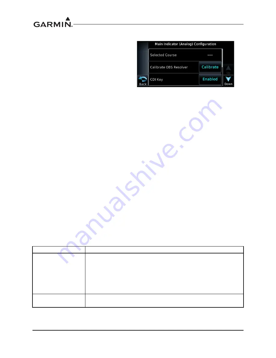
Main Indicator (Analog) Configuration Page
Access the Main Indicator (Analog)
Configuration page, as shown in Figure 6-8,
by touching the ‘Main Indicator (Analog)’
key on the GTN Setup page. This page allows
you to calibrate the OBS resolver, enable the
CDI key, selected course for GPS and/or
VOR/LOC, and configure the V-Flag state.
The following fields can be configured:
CALIBRATE OBS RESOLVER
To calibrate the OBS resolver, touch the
‘Calibrate’ key from the Main CDI
Configuration page. Next, select 150
˚
on the OBS, then touch the ‘OK’ key, as prompted on the display.
After the OBS resolver is finished calibrating, the GTN will display ‘OBS Resolver Calibration Complete’.
Touch ‘OK’ after the calibration is complete. Verify OBS operation by checking that the course displayed
on the GTN is within 2° of the selected course.
CDI KEY
If it is desired to disable the CDI key, touch the key to the right of ‘CDI Key’ to toggle between enabling
and disabling the CDI key. Disabling the CDI key removes the CDI key from the screen and sets the CDI/
VDI outputs always to GPS. This may be necessary for certain EFIS systems where navigation sensor
selection must be accomplished on the EFIS or its control panel.
SELECTED COURSE FOR GPS
If it is desired to ignore a selected course input for GPS operation in OBS mode, touch the key to the right
of ‘Selected Course for GPS’ until ‘Ignored’ is displayed on the key.
SELECTED COURSE FOR VOR/LOC
If it is desired to ignore a selected course input such that the VOR valid flag is dependent only on a valid
VOR signal, with lateral deviation calculated by another display device, touch the key to the right of
‘Selected Course for VLOC’ until ‘Ignored’ is displayed on the key.
V-FLAG STATE
Select either Normal or Declutter for the V-Flag State by touching the key until the desired selection is
displayed on the key.
Selection
Description
Declutter
Whenever vertical deviation is invalid, the vertical deviation bar is parked in
the maximum UP position and the vertical flag is removed from view, except
in the following cases: (i) the CDI is in VLOC mode and an ILS frequency is
tuned, or (ii) the CDI is in GPS mode and a GPS approach with vertical
guidance is active. In these cases, whenever the vertical deviation is invalid,
the vertical deviation bar parks in the centered position and the vertical flag is
shown.
Normal
Whenever vertical deviation is invalid the vertical deviation bar parks in the
centered position and the vertical flag is shown.
Figure 6-8. Main Indicator (Analog) Configuration
Page
Содержание GTN 625
Страница 1: ...190 01004 02 February 2013 Revision F GTN 625 635 650 TSO Installation Manual ...
Страница 2: ......
Страница 6: ...GTN 625 635 650 TSO Installation Manual 190 01004 02 Page D Rev F This page intentionally left blank ...
Страница 18: ...GTN 625 635 650 TSO Installation Manual 190 01004 02 Page xii Rev F This page intentionally left blank ...
Страница 54: ...GTN 625 635 650 TSO Installation Manual 190 01004 02 Page 2 2 Rev F This page intentionally left blank ...
Страница 66: ...GTN 625 635 650 TSO Installation Manual 190 01004 02 Page 3 12 Rev F This page intentionally left blank ...
Страница 80: ...GTN 625 635 650 TSO Installation Manual 190 01004 02 Page 4 14 Rev F This page intentionally left blank ...
Страница 110: ...GTN 625 635 650 TSO Installation Manual 190 01004 02 Page 5 30 Rev F This page intentionally left blank ...
Страница 186: ...GTN 625 635 650 TSO Installation Manual 190 01004 02 Page 7 2 Rev F This page intentionally left blank ...
Страница 188: ...GTN 625 635 650 TSO Installation Manual 190 01004 02 Page A 2 Rev F This page intentionally left blank ...
Страница 198: ...GTN 625 635 650 TSO Installation Manual 190 01004 02 Page B 10 Rev F This page intentionally left blank ...
Страница 200: ...GTN 625 635 650 TSO Installation Manual 190 01004 02 Page C 2 Rev F This page intentionally left blank ...
Страница 206: ...GTN 625 635 650 TSO Installation Manual 190 01004 02 Page C 8 Rev F This page intentionally left blank ...
Страница 208: ...GTN 625 635 650 TSO Installation Manual 190 01004 02 Page D 2 Rev F This page intentionally left blank ...
Страница 242: ...GTN 625 635 650 TSO Installation Manual 190 01004 02 Page D 36 Rev F Figure D 24 Reserved ...
Страница 250: ...GTN 625 635 650 TSO Installation Manual 190 01004 02 Page D 44 Rev F Figure D 32 Reserved ...
Страница 252: ...GTN 625 635 650 TSO Installation Manual 190 01004 02 Page D 46 Rev F This page intentionally left blank ...
Страница 253: ......
Страница 254: ......


